Crane trolleys
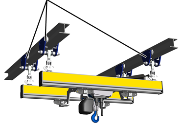
The number of trolleys required and their arrangement is specified in the planning documents.
The crane girder then later runs with the trolleys along the I-beams.
|
Crane trolleys |
|
|
| |
For the installation of the trolleys on the I-beam, see the product manual “Push trolley HF / Electric trolley EF” in the section “Installing the trolley on the I-beam”.
On both I-beams:
|
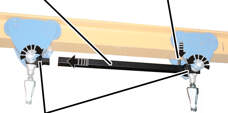
Coupling bar |
Bolt | |
|
| ||
|
Coupling |
| |
 Turn each coupling so that
it is facing the respective other trolley.
Turn each coupling so that
it is facing the respective other trolley.
Insert the coupling rod
between the couplings.
Insert the bolts (2x)
through the coupling rod and couplings from above.
|
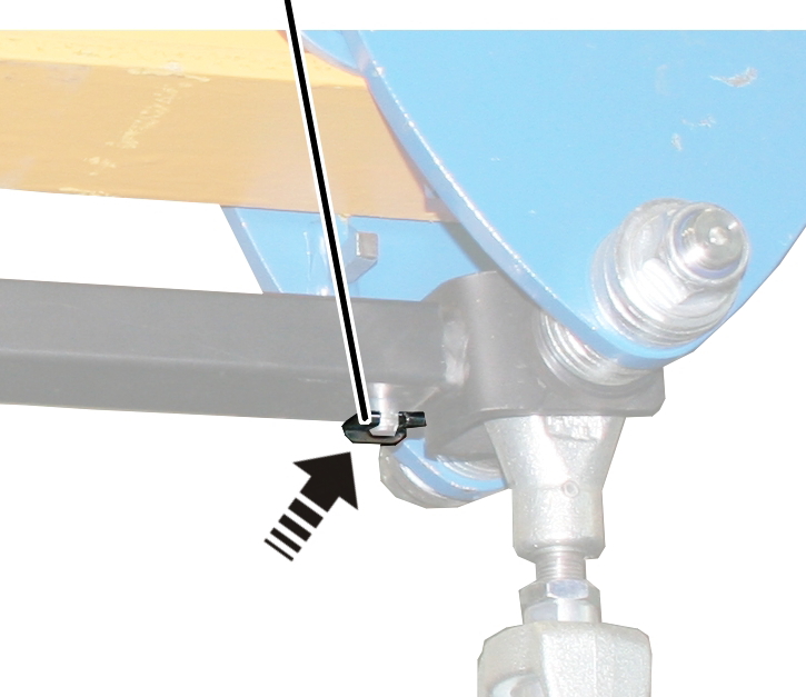
SL safety clip |
|
|
| |
 Secure bolts with SL
safety clips (2x)
Secure bolts with SL
safety clips (2x)