Where a trolley travel limit switch is to be mounted is specified in the planning documents.
The travel limit switches are then installed.
|
|
Where a trolley travel limit switch is to be mounted is specified in the planning documents. |
The trolley has a travel limit switch with braking and/or shut-down functions. This prevents the trolley from running against the end of the crane girder and causing the load to swing heavily.
There are two different attachment options for the travel limit switch:
─ One cross-type limit switch on the HBF drive.
─ Two cross-type limit switches on the HB profile rail.
Once the trolley can run with maximum load capacity:
 Suspend a load on the load
hook which corresponds to the maximum load capacity of the crane.
Suspend a load on the load
hook which corresponds to the maximum load capacity of the crane.
Determine the necessary
distance between switching lug and crane girder end:
For braking function: the distance must be long enough so that the trolley is only running at a low speed shortly before the crane girder end.
For shut-down: the distance must be long enough so that the trolley is at a standstill shortly before the crane girder end.
Add 0.5 m to 1 m
to the calculated distance. This will compensate for the brake wear on the
drive.
This section only applies if the cross-type limit switch is to be installed as a trolley travel limit switch for a trolley power supply using a festoon cable system.
The cross-type limit switch with connection cable is integrated in the power supply. The switching lugs are installed on the HB profile rails.
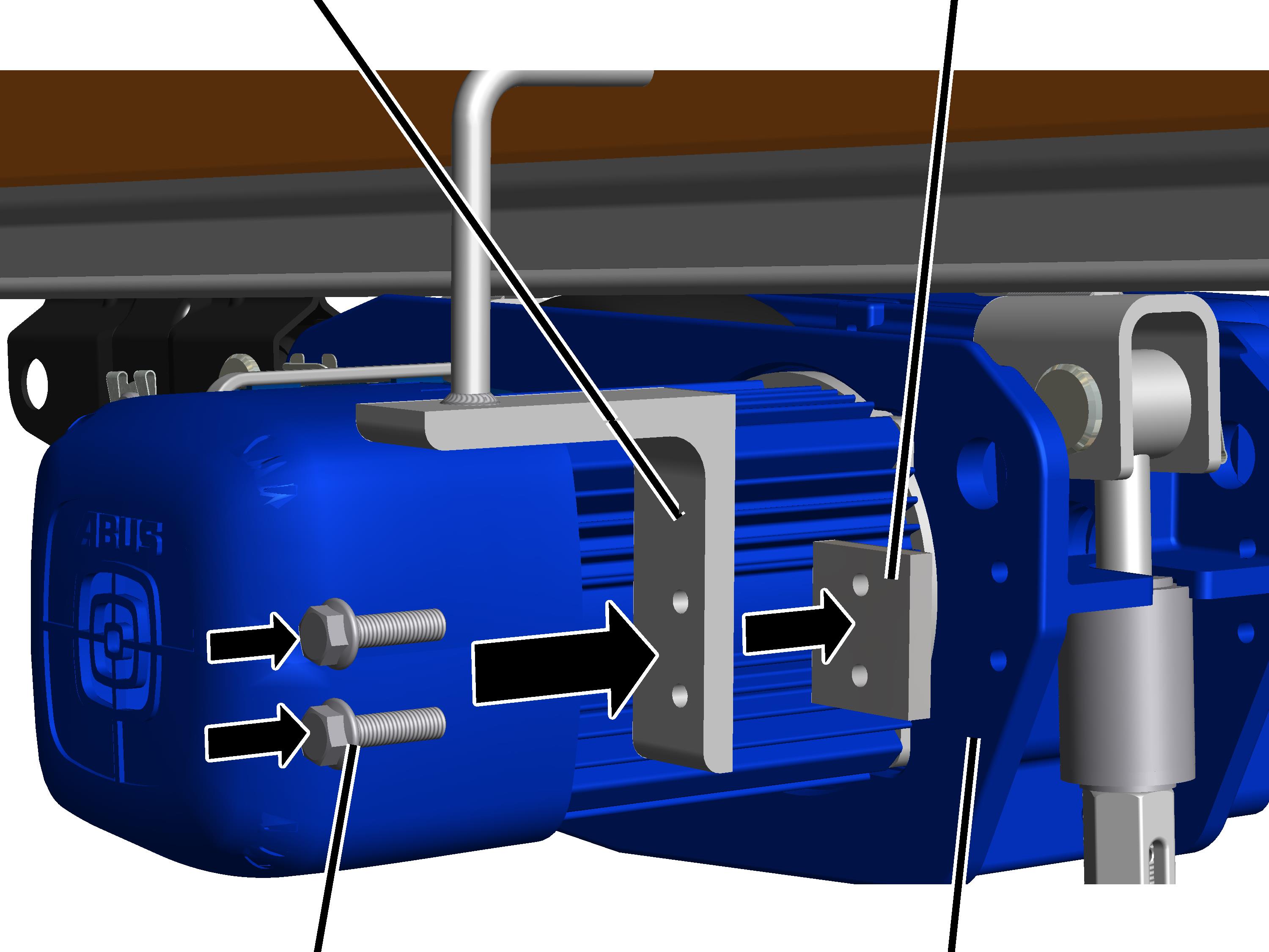
On the HBF drive on the side turned away from the chain hoist:
|
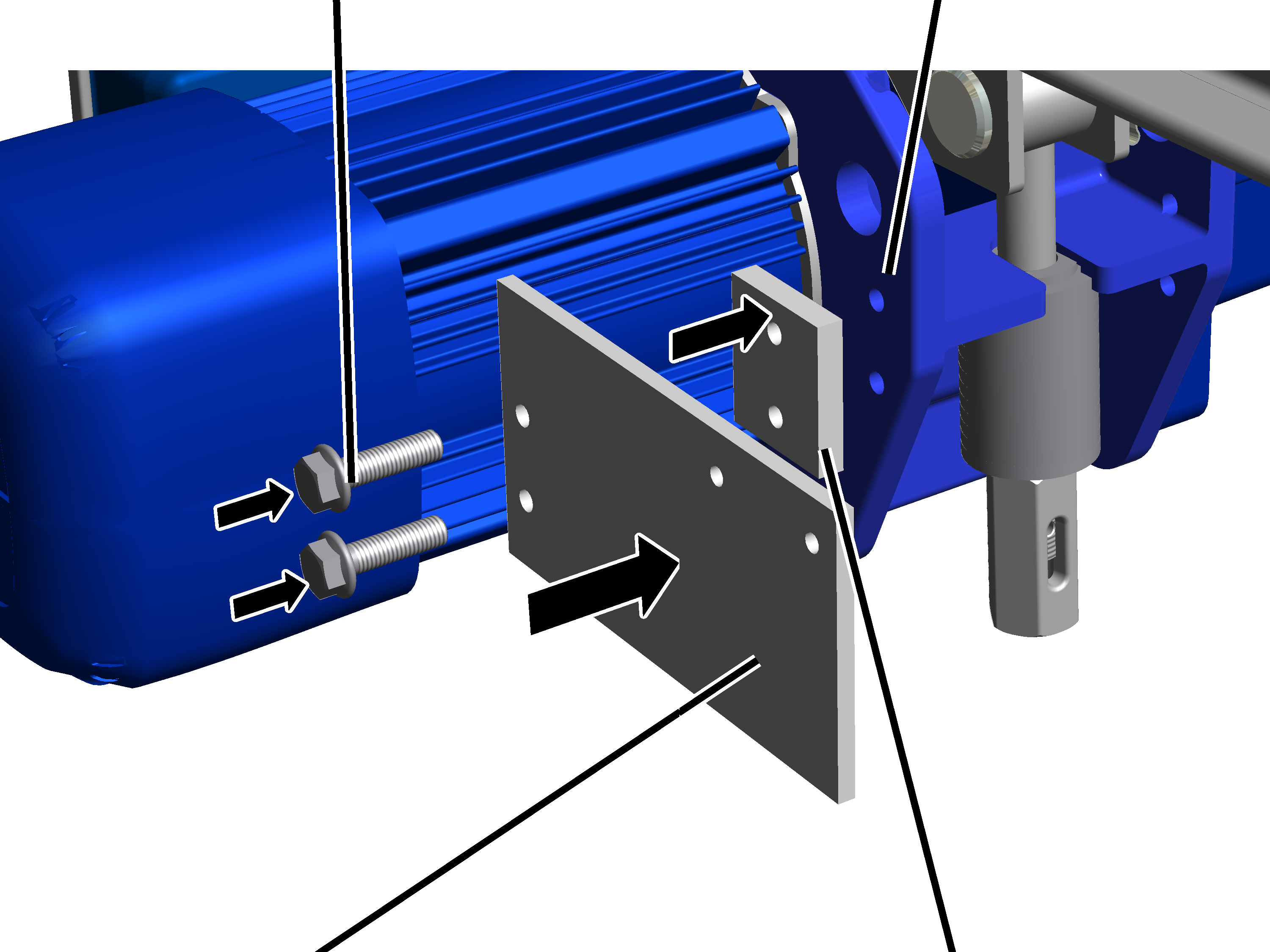
Rib screws M6x25 |
HBF drive |
|
| |
|
Mounting plate |
Spacer plate |
 Bolt the mounting plate
and spacer plate onto the HBF drive with the M6x25 rib screws (2x).
15 Nm.
Bolt the mounting plate
and spacer plate onto the HBF drive with the M6x25 rib screws (2x).
15 Nm.
|
|
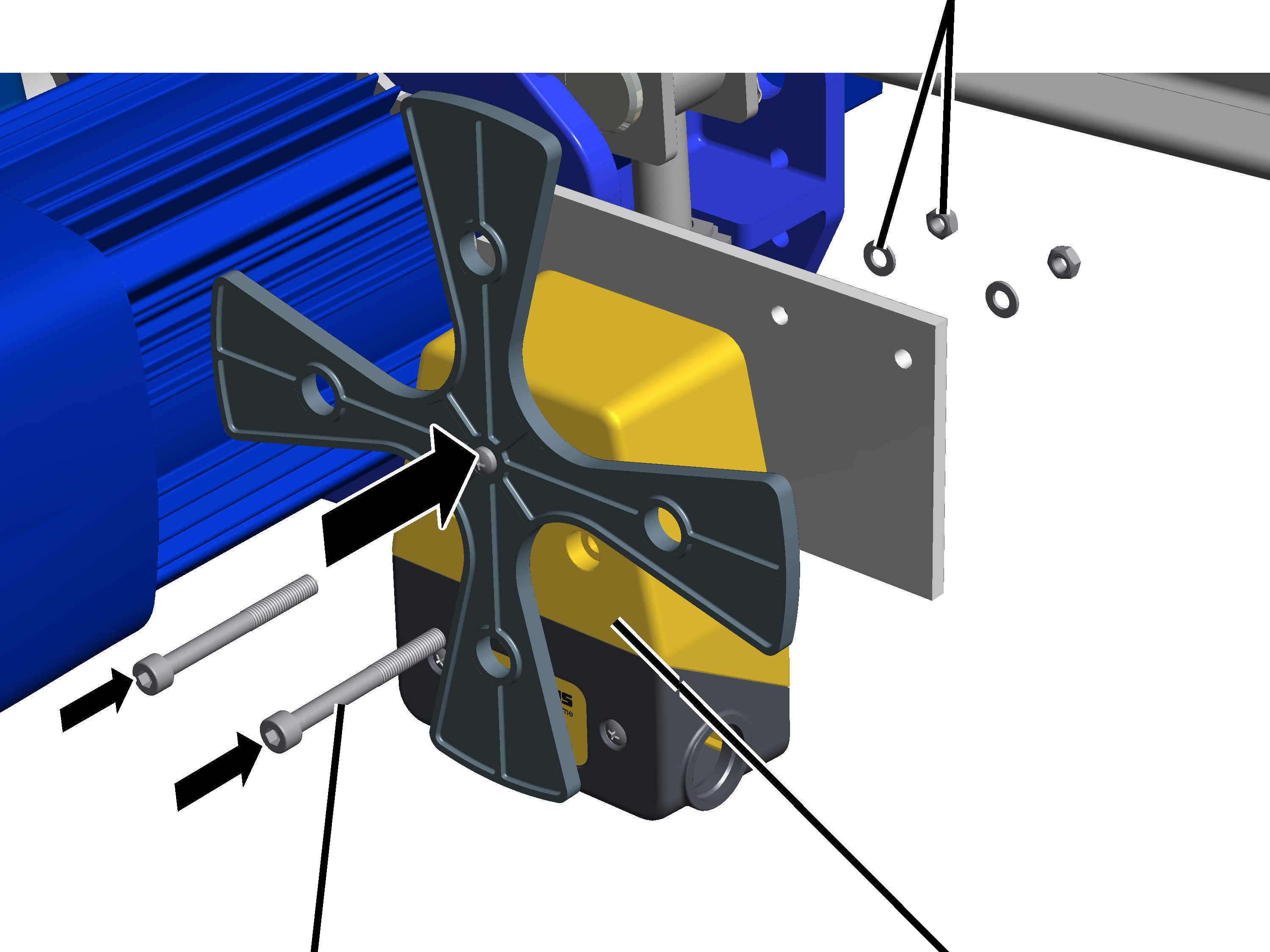
Hexagonal nuts and washers |
|
| |
|
Fillister-head screws M5x50 |
Cross-type limit switch |
Screw on the cross-type
limit switch with the M5x50 fillister-head screws (2x), washers and hexagonal
nuts. 3 Nm.
|
|
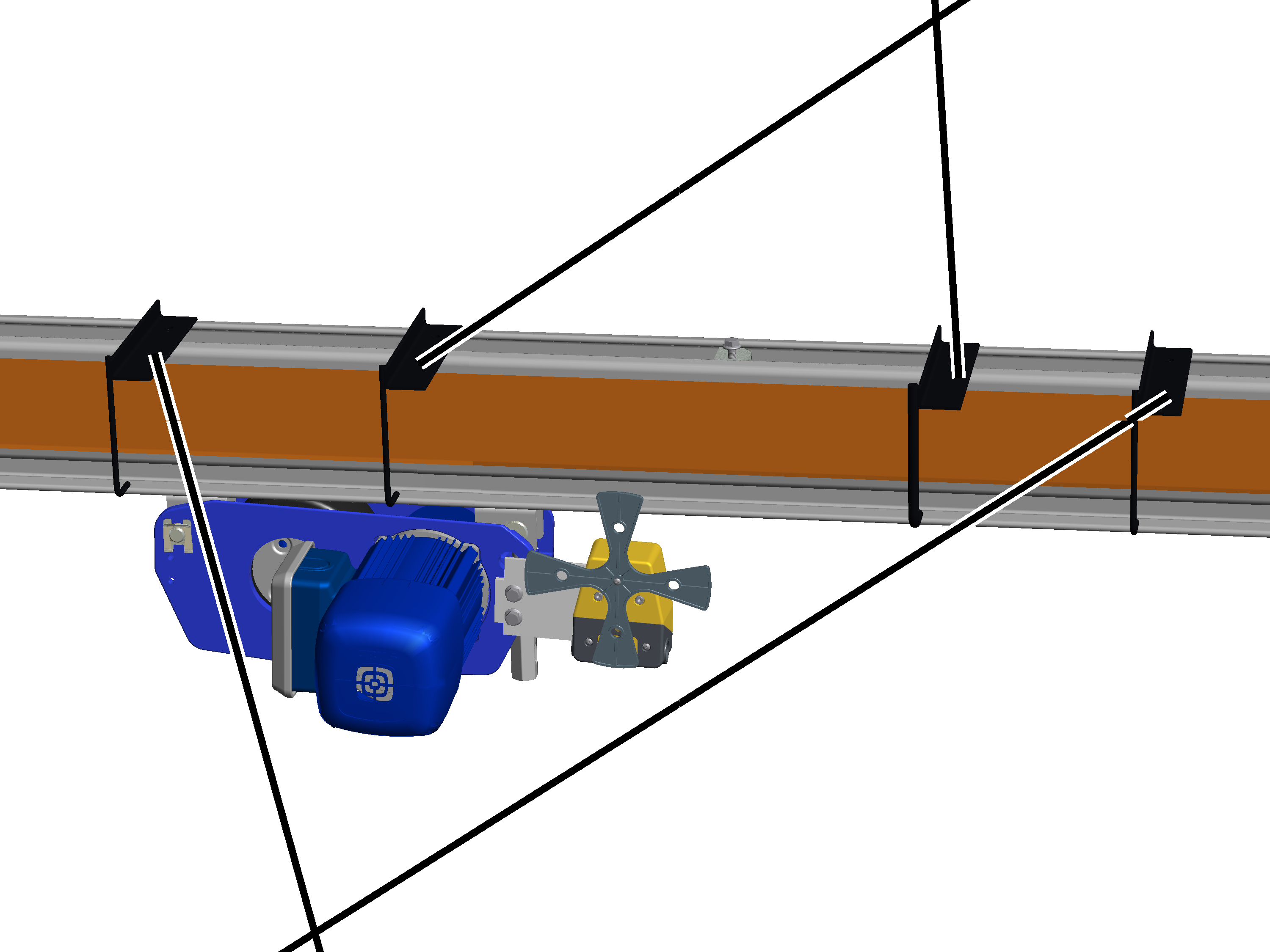
Switching lugs for braking function |
|
| |
|
Switching lugs for shut-down |
|
Position the switching
lugs so that the drive will switch at the desired switching points.
─ For braking function: two switching lugs are required for braking.
In the traversing range, the cross-type limit switch is at position “0”; in the left braking area, the cross-type limit switch is at position “1” and in the right braking area at position “5”.
─ For the braking and shut-down functions: four switching lugs are required for braking and shut-down.
The cross-type limit switch is also at position “2” in the left shut-down area and at position “4” in the right shut-down area.
|
|
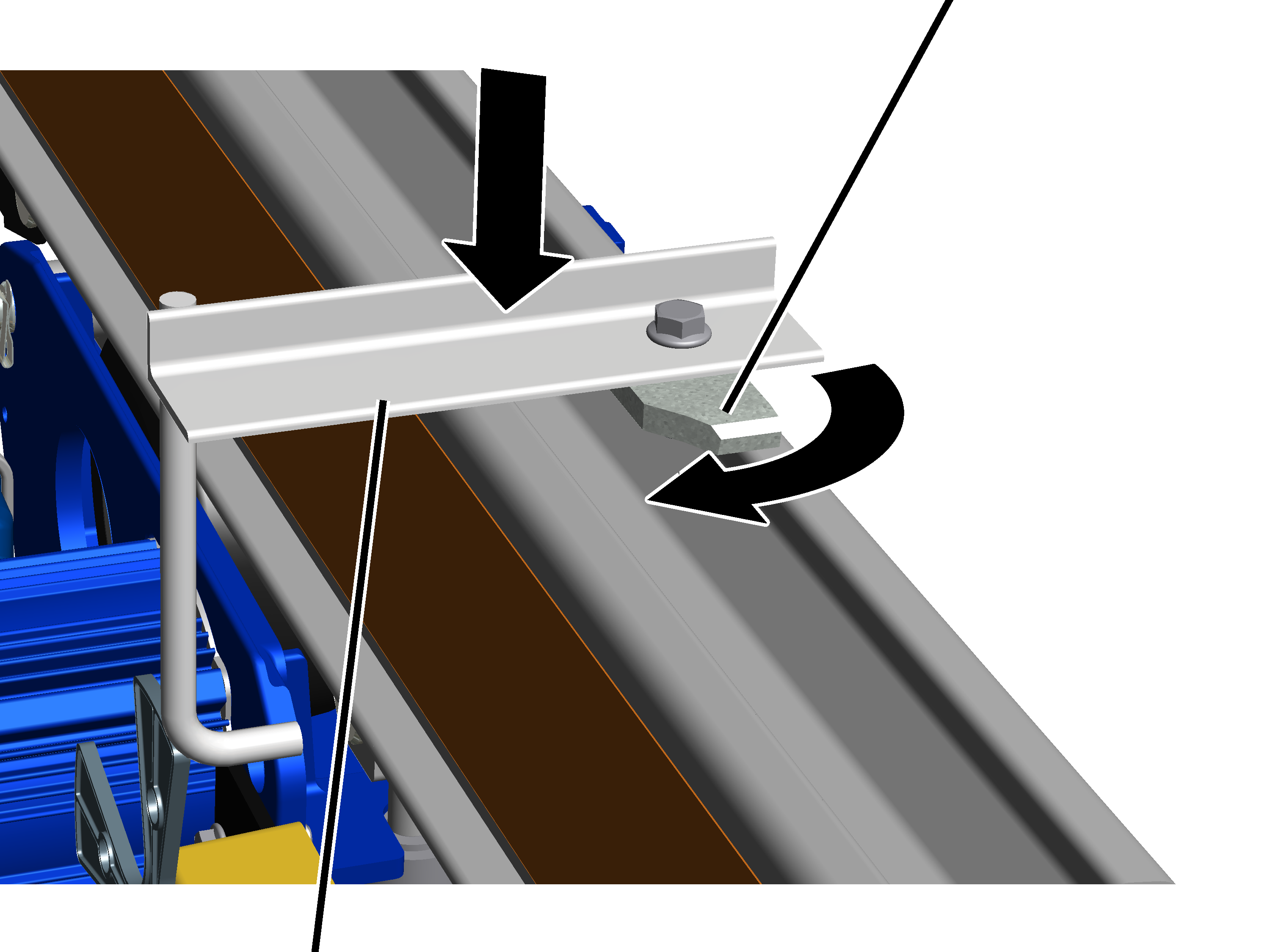
Head nut |
|
| |
|
Switching lug |
|
Insert switching lugs from
above into the profile head of the HB profile rail. In doing so, bring the head
nut into the profile head.
Turn the head nuts so that
they lay crosswise in the profile head.
Screw the M8x20 rib screws
to the head nuts. 30 Nm.
This section only applies if the trolley travel limit switches must be installed on the HB profile rail. This is the case if the trolley power supply is using a conductor system for a KS30 panel.
On the HBF drive on the side turned away from the chain hoist:
|
Switching lug |
Spacer plate |
|
| |
|
Rib screw |
HBF drive |
Bolt the switching lug and
spacer plate onto the HBF drive with M6x30 rib screws (2x). 15 Nm.
|
Cross-type limit switch for travel direction toward left |
Cross-type limit switch for travel direction toward right |
|
| |
|
|
Switching lugs for braking and shut-down |
Position the cross-type
limit switches so that the drive will switch at the desired switching
points.
─ For braking function: two cross-type limit switches and one switching lug are required for braking.
The switching lug switches the braking in the respective travel direction.
─ For braking and shut-down: two cross-type limit switches and two switching lugs are required for braking and shut-down.
In the respective travel direction, the first switching lug switches the braking and the second switching lug then switches the shut-down.
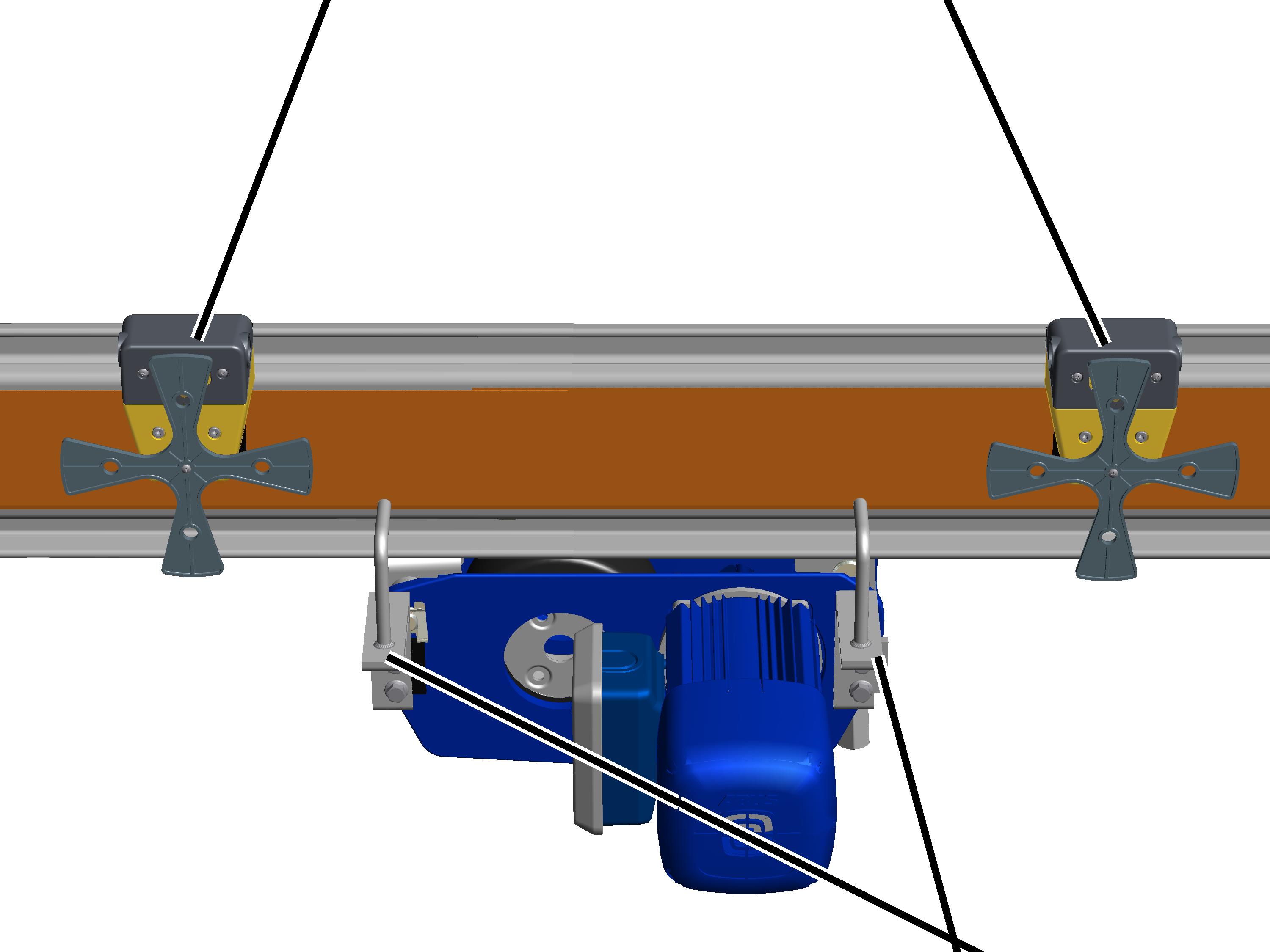
─ The cross-type limit switch with the short connection cable is mounted on the crane girder on the side on which the control is installed. The cross-type limit switch with the longer connection cable is mounted on the opposite end of the crane girder.
|
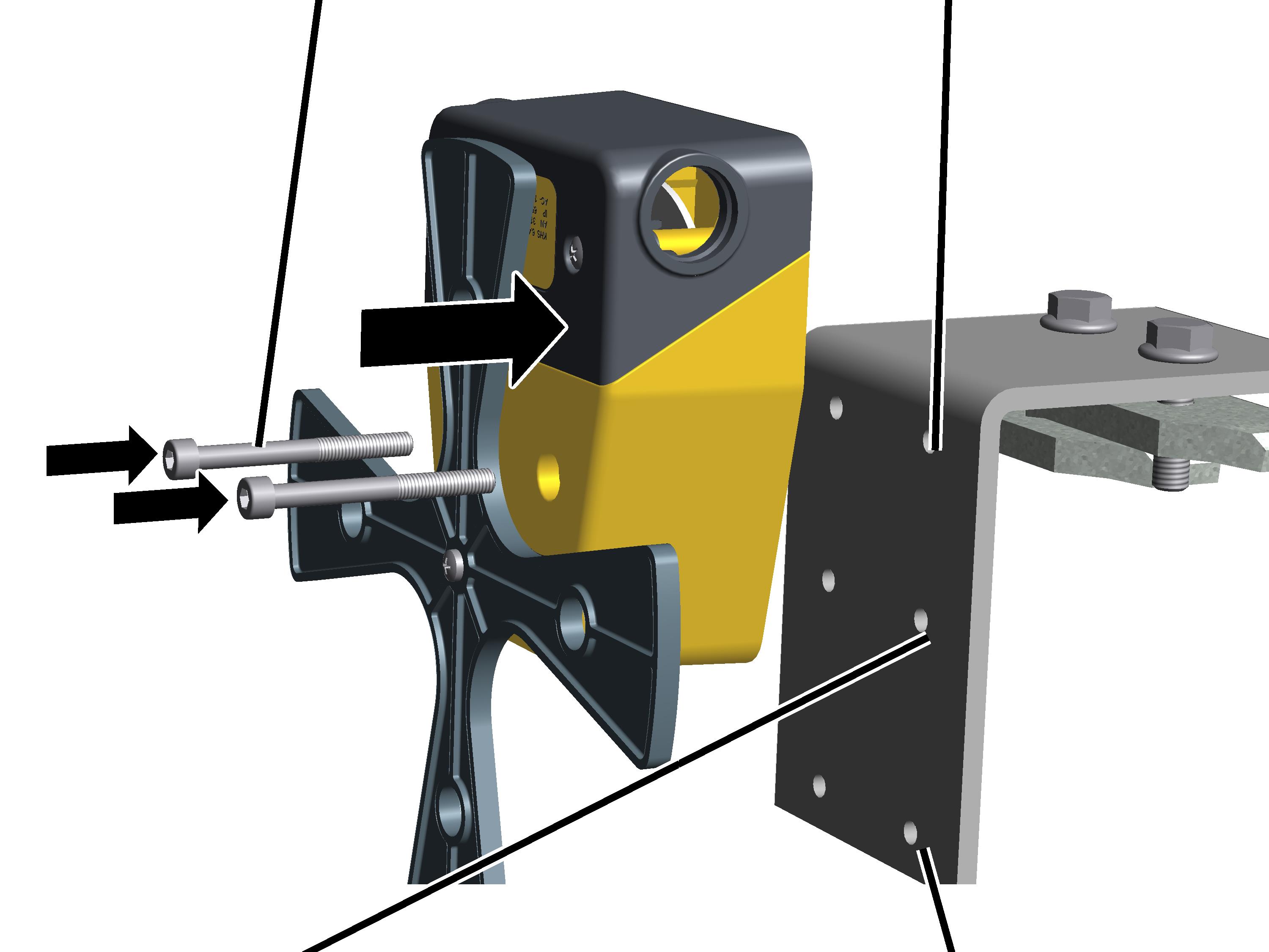
Fillister-head screws |
Drilled holes for HB150 |
|
| |
|
Drilled holes for HB190 |
Drilled holes for HB240 |
Screw the cross-type limit
switch with the M5x50 fillister-head screws, washers and M5 hexagonal nuts (each
2x) to the mounting bracket. 3 Nm.
─ For HB150: use the upper drilled holes.
─ For HB190: use the middle drilled holes.
─ For HB240: use the lower drilled holes.
|
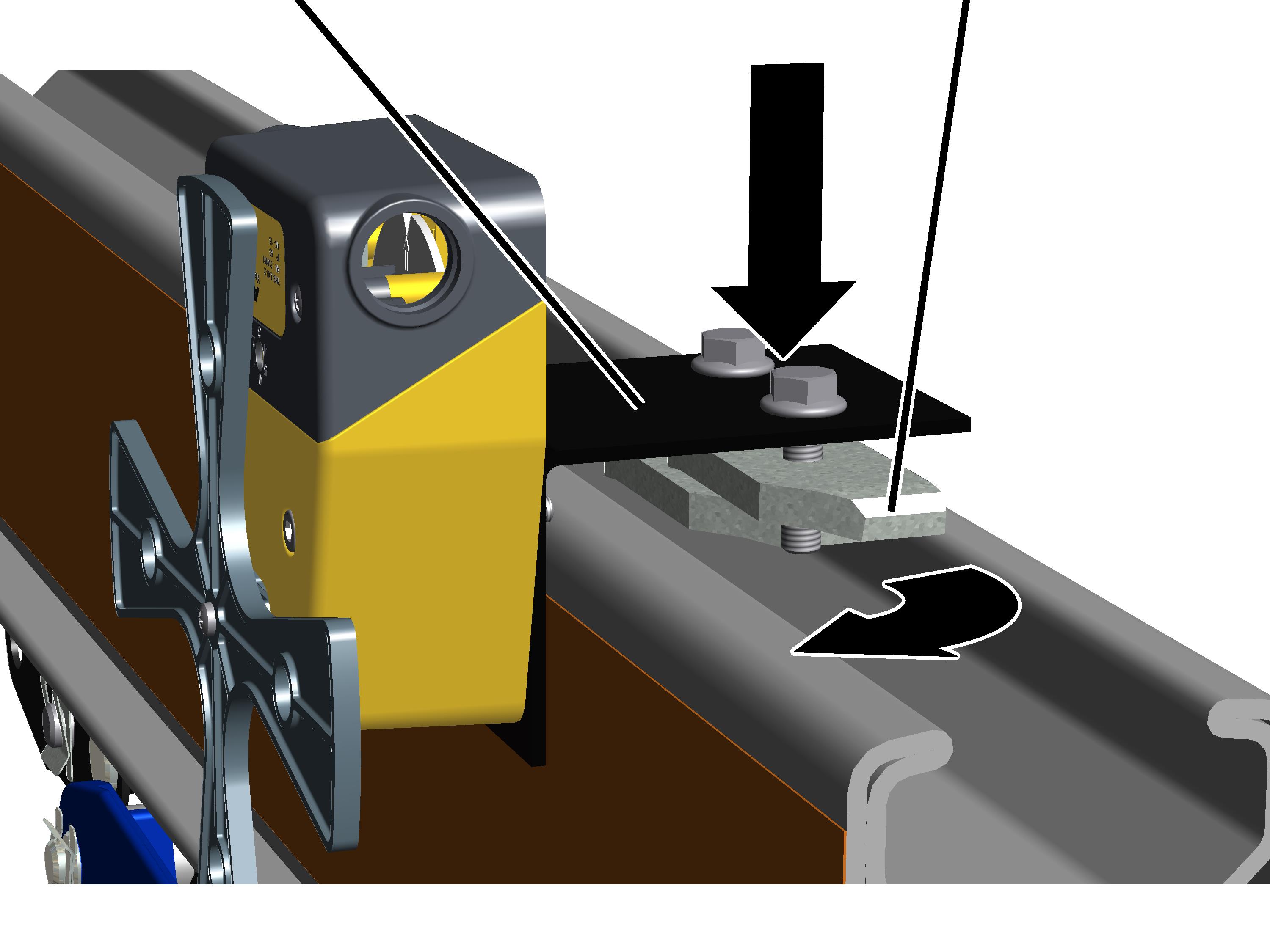
Mounting bracket with cross-type limit switch |
Head nuts (2x) |
|
| |
Insert the mounting
bracket with cross-type limit switch from above in the profile head of the HB
profile rail. In doing so, bring the head nuts (2x) into the profile head.
Turn the head nuts so that
they lay crosswise in the profile head.
Tighten the rib screws on
the head nuts. 25 Nm.