Only for trolley frames with normal overall height
The two HB profile rails are stabilised against each other with two track bracings.
|
|
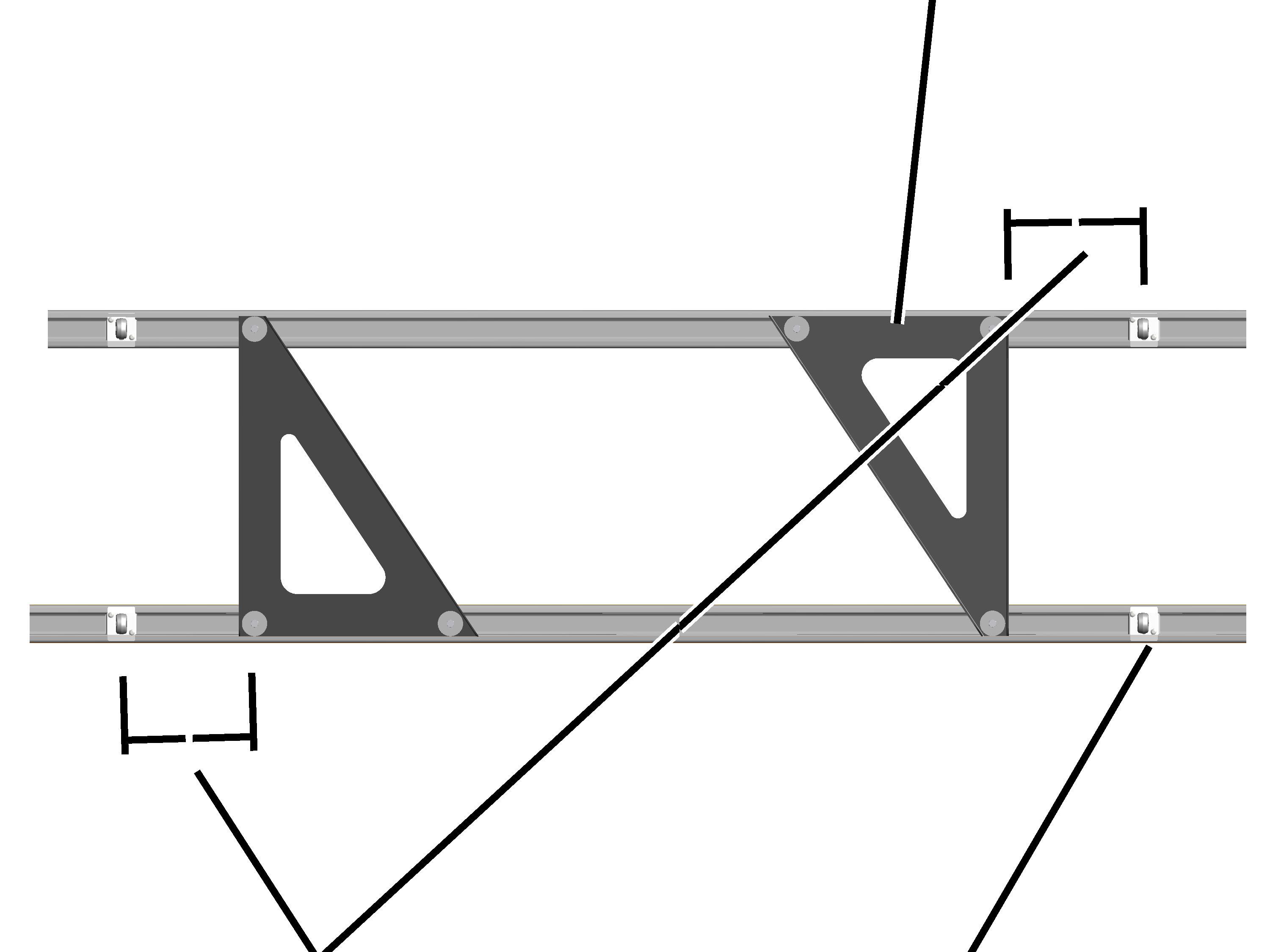
The figures show the assembly of a track bracing for a track gauge of 700 mm. For a track gauge of 850 mm, the assembly does not essentially differ. |

Installing the track bracing
On the left and right at the end of the HB profile rail:
|
|
Track bracing |
|
| |
|
Spacing 220 mm |
Crane girder suspension (or profile link) |
 Rotate the track bracing
so that it appears as shown in the figure.
Rotate the track bracing
so that it appears as shown in the figure.
Lay the track bracing on
the inner side of the crane girder suspensions (or profile links) on the profile
head.
Move the track bracing so
that it has a distance of 220 mm to the crane girder suspension (or profile
link).
|
Track bracing |
Head nut |
|
| |
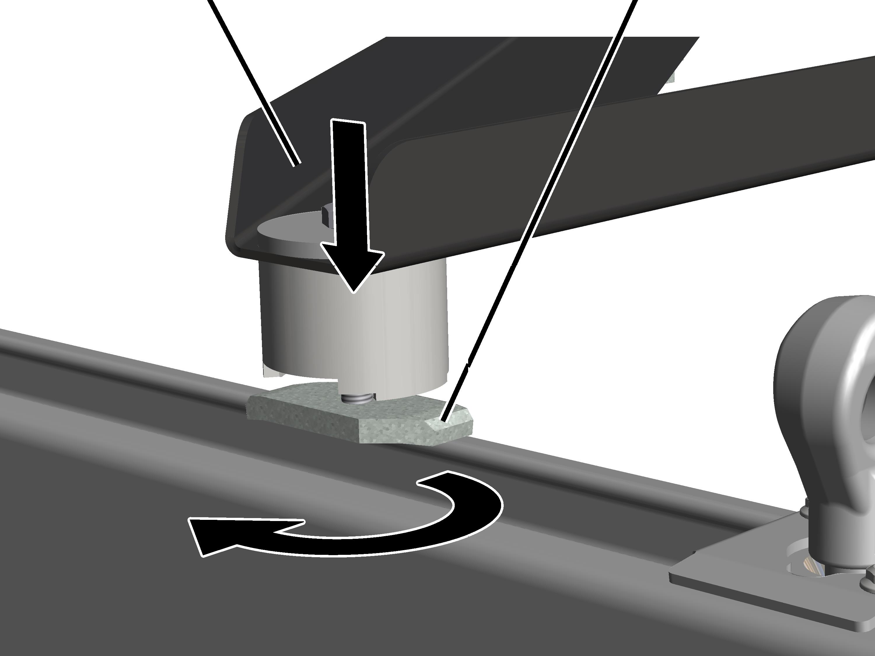
Turn
the head nut in the longitudinal direction and insert in the profile head from
above.
● The head nut extends into the profile head.
Screw the hexagon head
screws M10x70 tight. 35 Nm.
● The head nut turns during fixing in the crosswise direction and is clamped tight in the profile head.