Now the control is installed. There are
different controls and different fastening options for the controls.
|

|
Whether and where a control is to be installed is
specified in the planning documents. The specified dimensions, positions
and clearances must be followed exactly.
Only with direct control: the position of the junction
box SVKR is not specified in the planning documents and must be determined
on site. |
The control is installed now so that in subsequent work steps
the lines can be laid exactly up to it.
|

|
Danger due to incorrect assembly.
If the control is installed in the wrong place, a
contactor may fail to switch off correctly. This can lead to malfunctions
on the crane.
Be sure to check the type of control and install
it as specified here. |
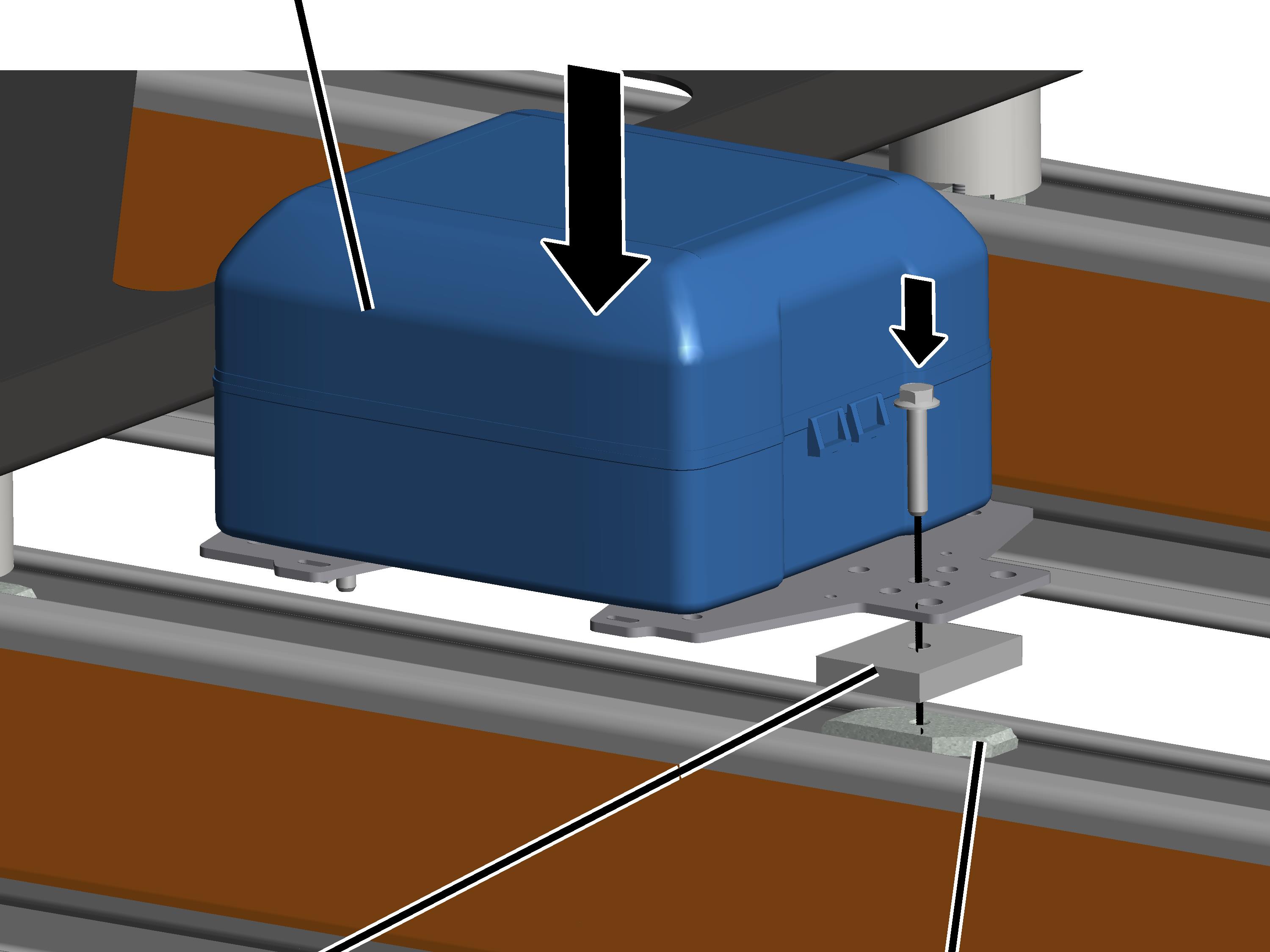
The junction box SVKR is installed flat on one of the HB
profile rails.
The exact position must be determined according to the other
installed components (e.g. track bracing). The junction box SVKR should be
installed on the side where the trolley drive is also located.
Installing the
junction box SVKR
On the side of the mains power supply and on the crane girder
with trolley power supply:
|
Junction
box SVKR |
|
|
|
|
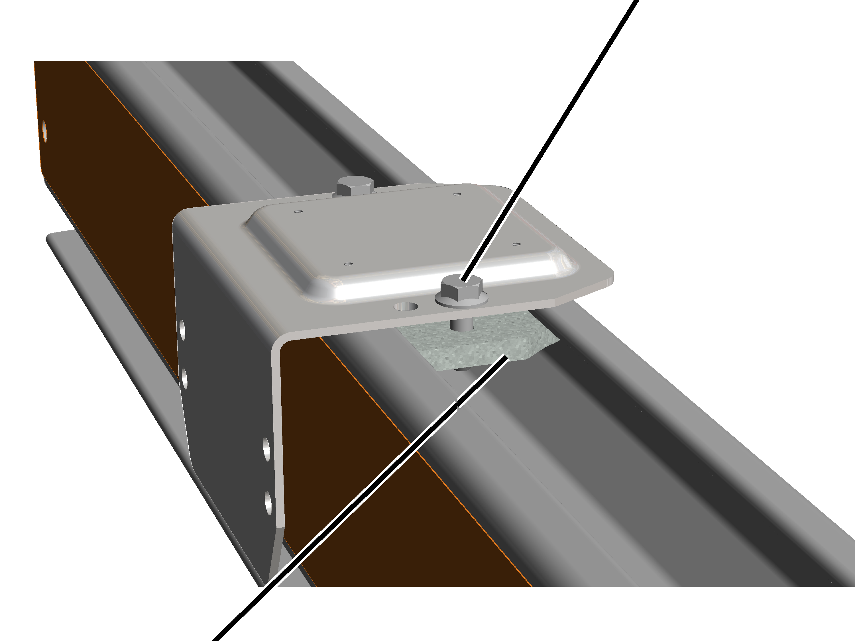
Plate |
Head
nut |
 Insert the rib screw M8x45 through one of the middle
drilled holes in the mounting plate.
Insert the rib screw M8x45 through one of the middle
drilled holes in the mounting plate.
Insert the plate from
below.
Screw the head nut loosely
onto the rib screw from below.
Insert junction box SVKR
from above into the profile head of the HB profile rail. In doing so, bring the
head nut into the profile head.
Screw the M8x45 rib screws
to the head nuts. 30 Nm.
● The head
nut turns during fixing in the crosswise direction and is clamped tight in the
profile head.
Only with terminal
boxes
If necessary, a terminal box is installed on the HB profile
rail. The terminal box is used to later directly connect the mains power supply
with the trolley power supply.
|
|
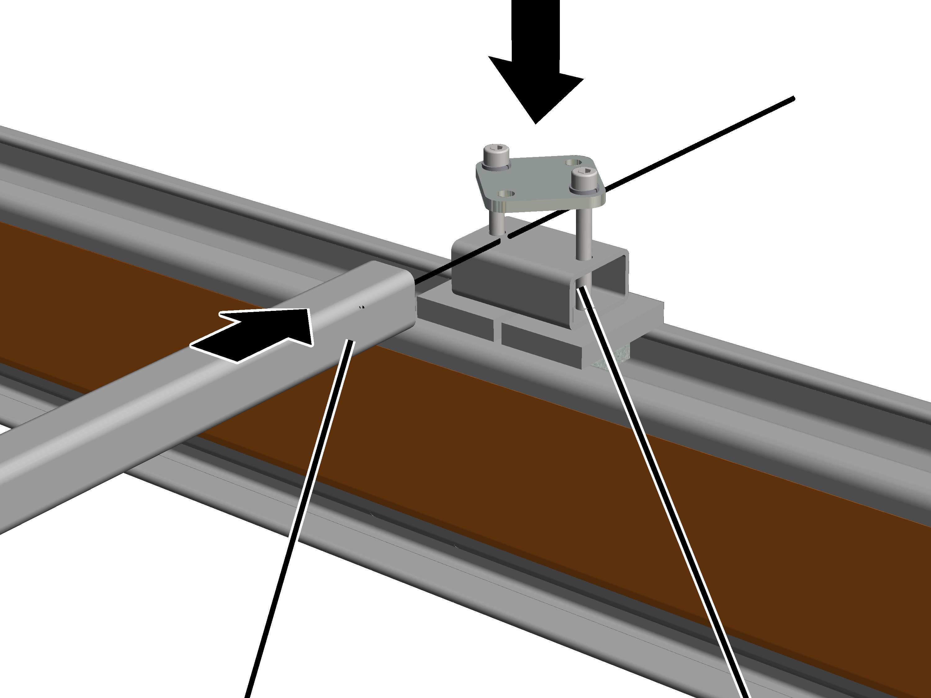
Rib
screw M8x25 |
|
|
|
Head
nut |
|
If required: insert rib
screw M8x25 (2x) in base plate and screw the head nut (2x) onto the rib screw
from below.
 Turn the head nut in the
longitudinal direction and lay the base plate on the profile head from
above.
Turn the head nut in the
longitudinal direction and lay the base plate on the profile head from
above.
● The head
nut extends into the profile head.
Tighten the rib screws to
25 Nm.
● The head
nut turns during fixing in the crosswise direction and is clamped tight in the
profile head.
|
|
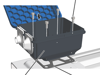
Fillister-head screw M4x10 |
|
|
|
Connector housing |
Seal |
Stick the self-adhering
seal under the connector housing.
Bolt the connector housing
onto the base plate with fillister-head screws M4x10 (4x).
Only for electronic
control
The electronic control is installed suspended from the HB
profile rail. The electronic control can also be mounted over a C-rail
system.
|

|
The position of the control is designated with a
symbol in the planning documents. The specified dimensions, positions and
clearances must be followed exactly. |
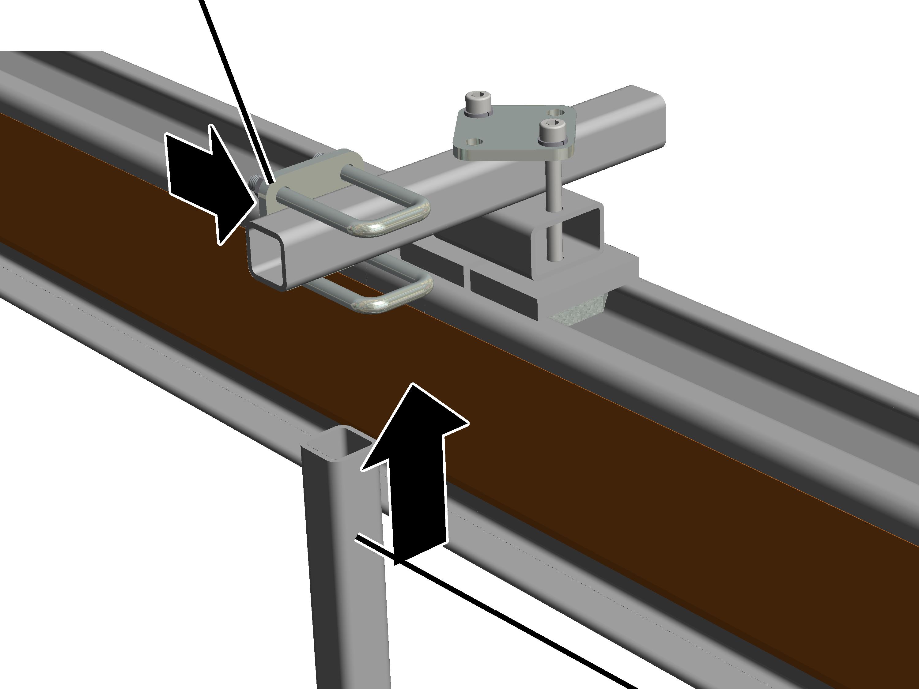
Installing the
clamping unit and square tubes on the profile head
|
|
|
Square
tube |
Clamping
unit in the profile head |
Insert the clamping unit
in the profile head as shown in the figure. In doing so, bring the head nut into
the profile head.
Push the square tube into
the clamping unit.
Do not yet screw the
clamping unit tight (so that the electronic control can still be aligned
later).
If the electronic control needs to be mounted over a C-rail
system, 12 cm clearance from the C-rail to the back of the electronic
control must be observed.
|
Pipe
clamp |
|
|
|
|
|
Vertical
square tube |
Push the pipe clamp onto
the square tube.
Push the vertical square
tube from below into the pipe clamp.
Screw the pipe clamp tight
to 25 Nm.
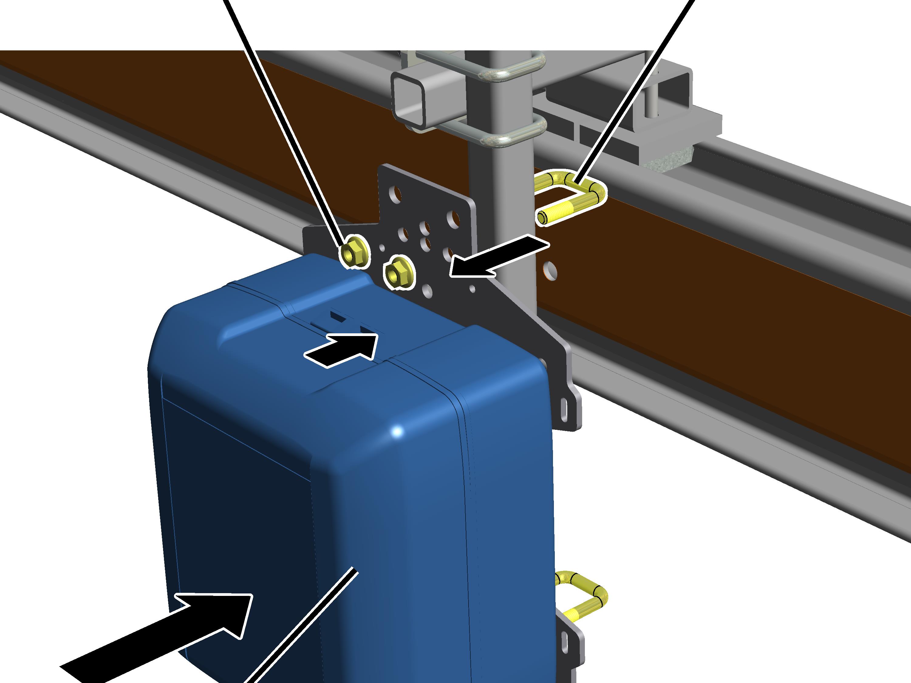
Installing the
electronic control
|
|
Malfunction in the event of horizontal
installation!
If the electronic control is installed
horizontally, the contactors in the electronic control may not switch
correctly. This could cause a malfunction.
Install the electronic control
vertically. |
|
Rib nut
M8 |
Threaded
bracket |
|
|
|
Electronic control |
Hold the electronic
control to the vertical square tube.
Push threaded brackets
(2x) from the back into the mounting plate.
Tighten the threaded
brackets from the front with the M8 rib nuts (4x).
Only with panel KS30
together with trolley frame with normal overall height
The control is installed suspended from the HB profile rail
on two square tubes that are bolted on crosswise over the two HB profile rails.
The control can also be mounted over a C-rail system.
|
|
The position of the control is designated with a
symbol in the planning documents. The specified dimensions, positions and
clearances must be followed exactly. |
|

|
The figures show the installation of a panel hanging
down. The installation of a panel pointing upwards, or a panel suspended
on the other side, does not essentially differ. |
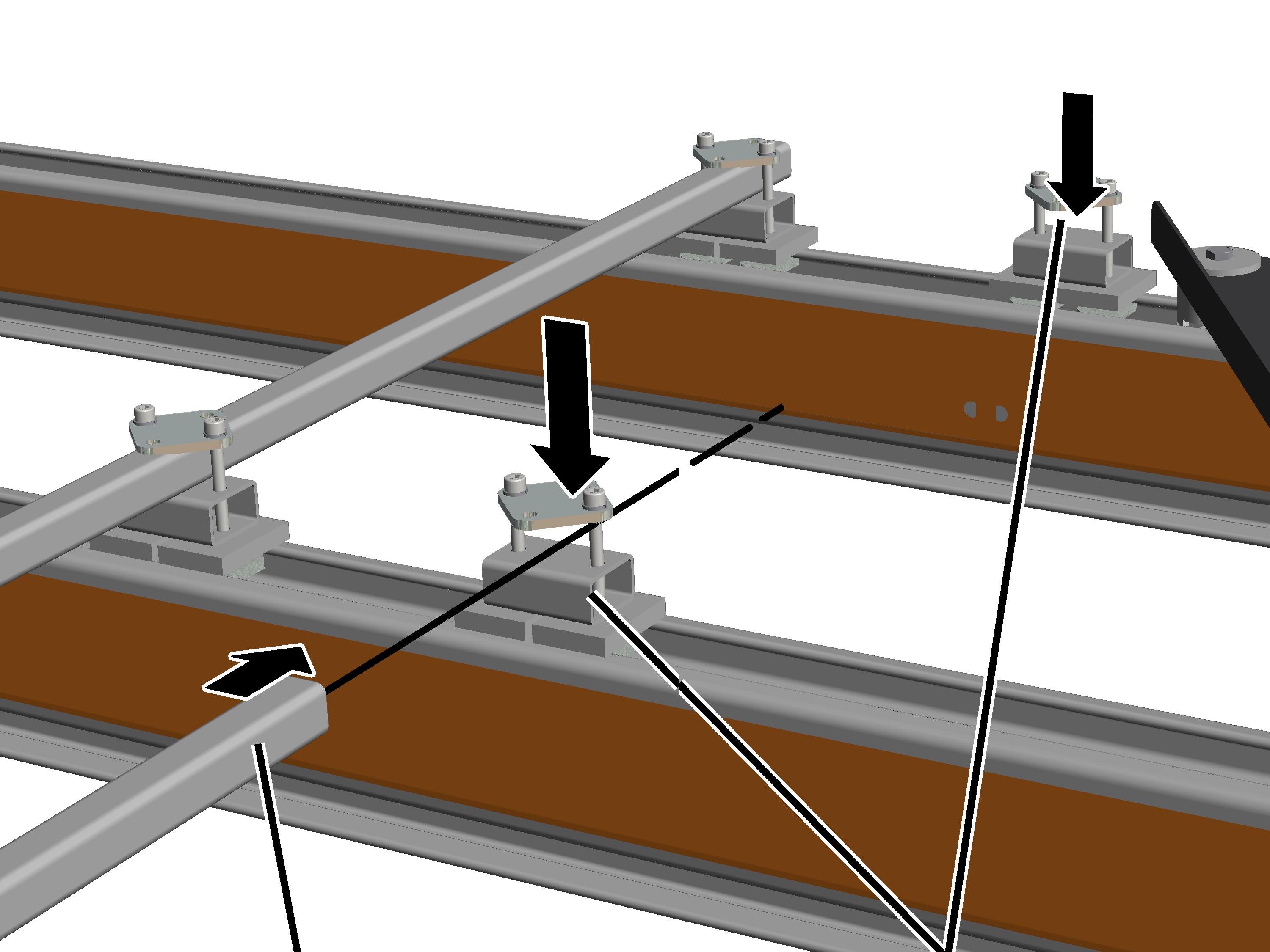
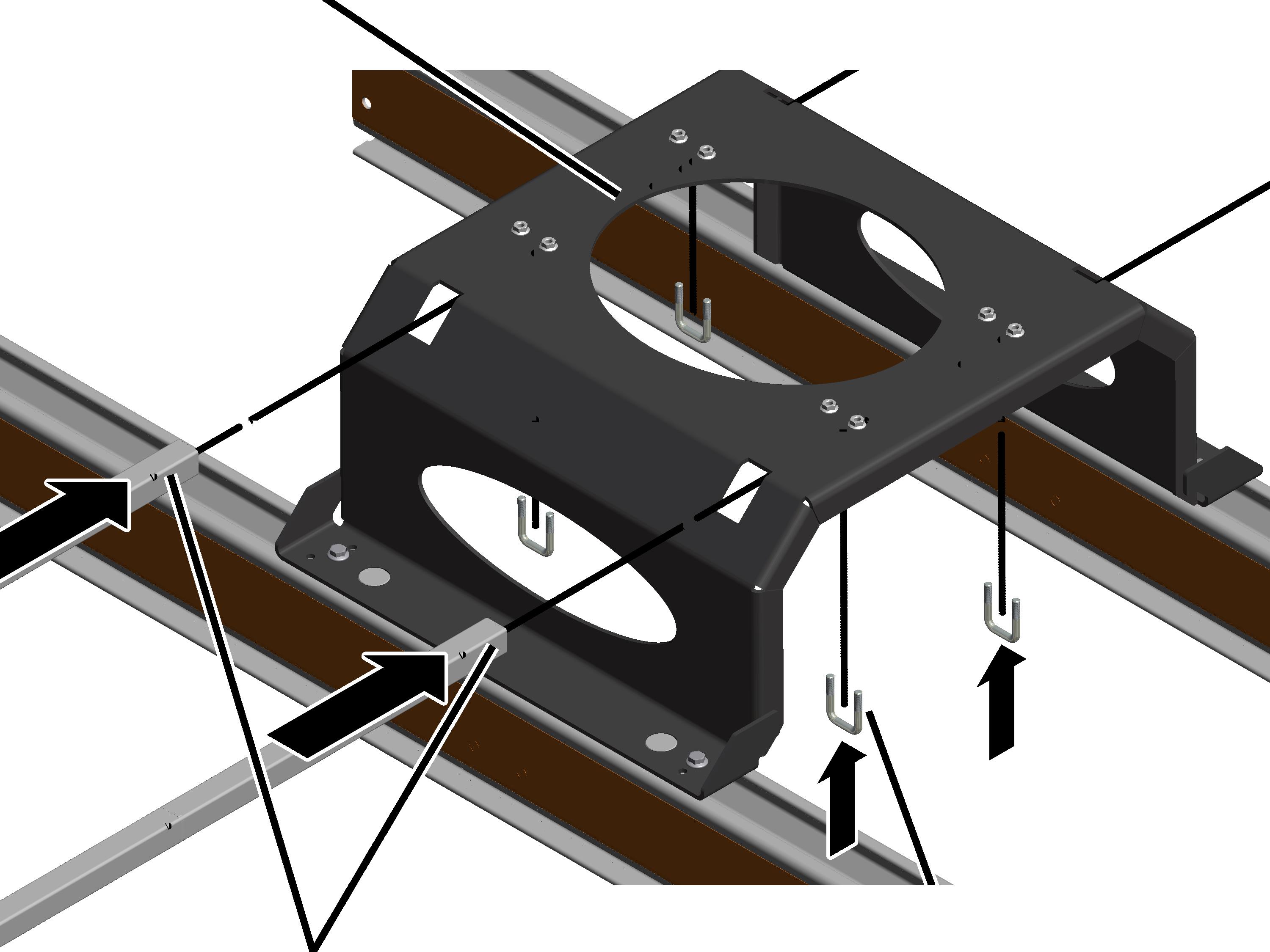
Installing
clamping units and square tubes on the profile head
|
|
|
Square
tube |
Clamping
unit in the profile head |
 Insert the clamping units
(4x) in the profile head as shown in the figure. In doing so, bring the head nut
into the profile head.
Insert the clamping units
(4x) in the profile head as shown in the figure. In doing so, bring the head nut
into the profile head.
Push the square tube into the clamping units.
Do not yet screw the
clamping units tight (so that the panel can still be aligned later).
If the panel needs to be mounted over a C-rail system, 12 cm
clearance from the C-rail to the back of the panel must be observed.
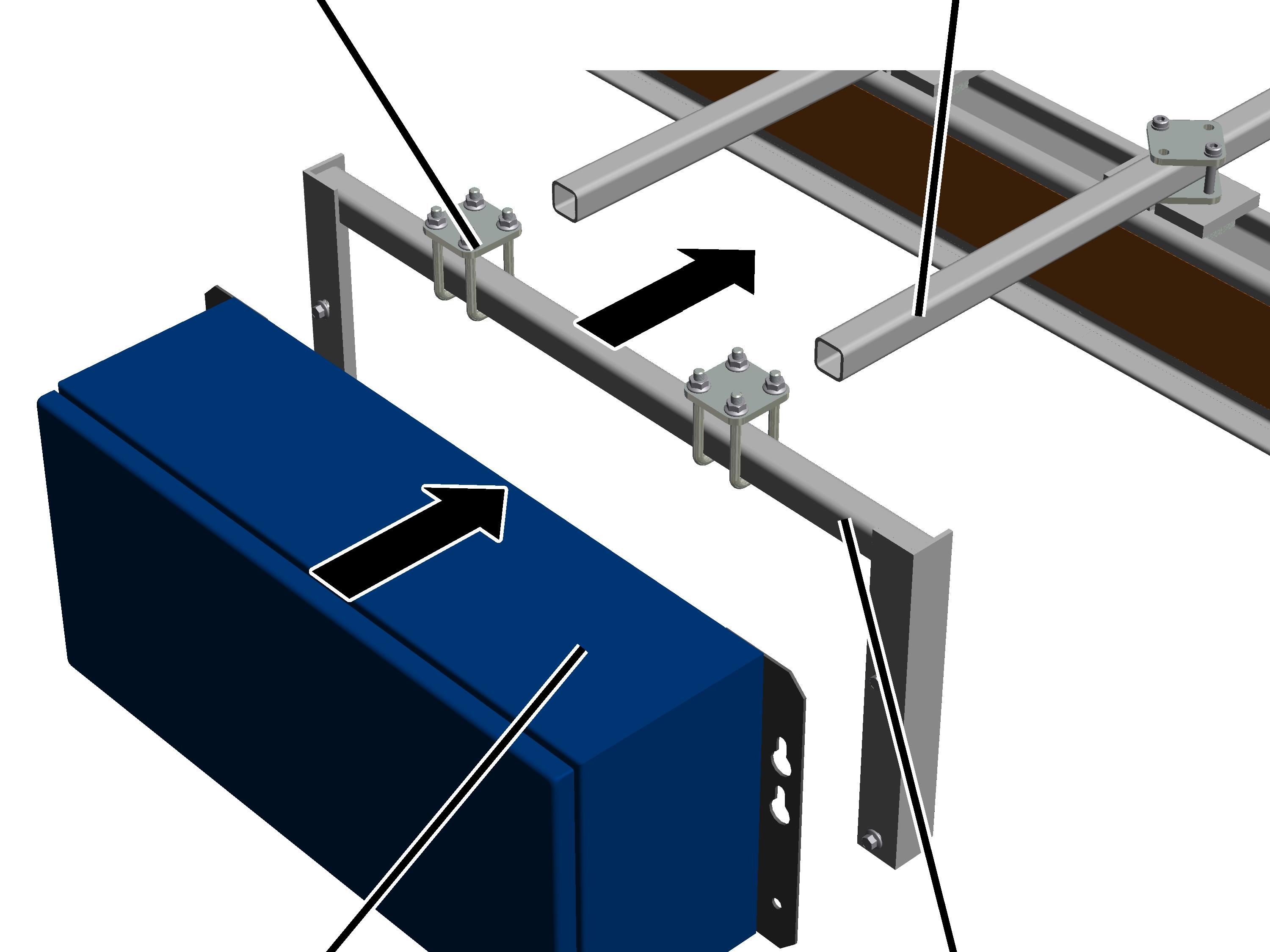
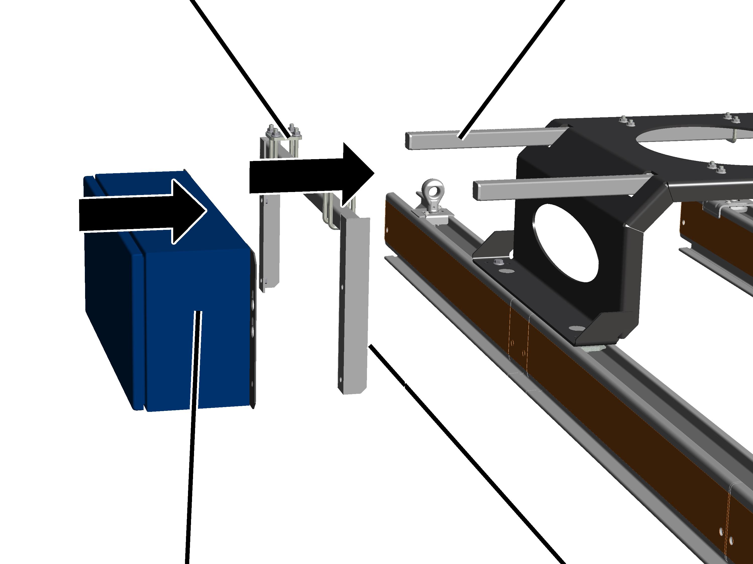
Installing the
panel
The figures show the installation of a panel hanging down.
Depending on the on-site conditions in the building, the panel can also be
installed on top of the HB profile rail.
|
Pipe
clamp |
Square
tube |
|
|
|
Panel |
Bracket |
Push the bracket with pipe
clamps (2x) onto the square tubes.
Push the square tube and
bracket together so that the panel hangs as close as possible to the track
bracing.
For HBF drive: push the
panel on the HB profile rail just far enough so that the HBF drive can still run
between panel and HB profile rail.
Bolt the clamping units in
the profile head and screw tight the pipe clamps (2x).
Bolt the panel onto the
bracket with the rib screws M8x16 (4x).
Only for panel KS30 together
with jacked up trolley frame
The control is installed so that it is suspended under the
bracing frame on two square tubes inserted through and bolted onto the bracing
frame.
|

|
The figures show the installation of a panel hanging
down. The installation of a panel pointing upwards, or a panel suspended
on the other side, does not essentially differ. |
Installing
square tubes on the bracing frame
|
Bracing
frame |
|
|
|
|
Square
tube |
Threaded
bracket |
 Push the square tubes (2x)
through the openings in the bracing frame.
Push the square tubes (2x)
through the openings in the bracing frame.
Push the square tubes in
until they come out of the openings on the other end.
Loosely screw on the
square tubes with threaded brackets (4x) and M8 rib screws (8x).
Do not yet screw the threaded brackets tight (so that the panel
can still be aligned later).
Installing the
panel
|
Pipe
clamp |
Square
tube |
|
|
|
Panel |
Bracket |
Push the bracket with pipe
clamps (2x) onto the square tubes.
Push the square tube and
bracket together so that the panel hangs as close as possible to the bracing
frame.
For HBF drive: push the
panel on the HB profile rail just far enough so that the HBF drive can still run
between panel and HB profile rail.
Bolt the threaded bracket
onto the bracing frame (4x) and tighten the pipe clamps (2x).
Bolt the panel onto the
bracket with the rib screws M8x16 (4x).
Only with power supply using
conductor system
For some control versions, a further junction box is required
on the trolley frame in addition to the control on the HB profile rail. This is
specified in the wiring diagram.
|
Trolley
frame |
|
|

|
|
|
Junction
box |
Hold the junction box with
the mounting plate to the trolley frame.
On one side of the trolley frame are threaded holes for
this.
Screw on the junction box
with the rib screws M10x16 (2x). 80 Nm.