Danger due the the trolley rolling away!
The trolley may roll away during jib arm installation, and injure persons, when it is not sufficiently secured.
Secure the trolley on the jib arm against rolling away.
All individual components have now been affixed to the jib arm. Now the jib arm can be installed on the supporting structure with the wall mounts.
|
|
Danger due the the trolley rolling away! The trolley may roll away during jib arm installation, and injure persons, when it is not sufficiently secured. Secure the trolley on the jib arm against rolling away. |
|
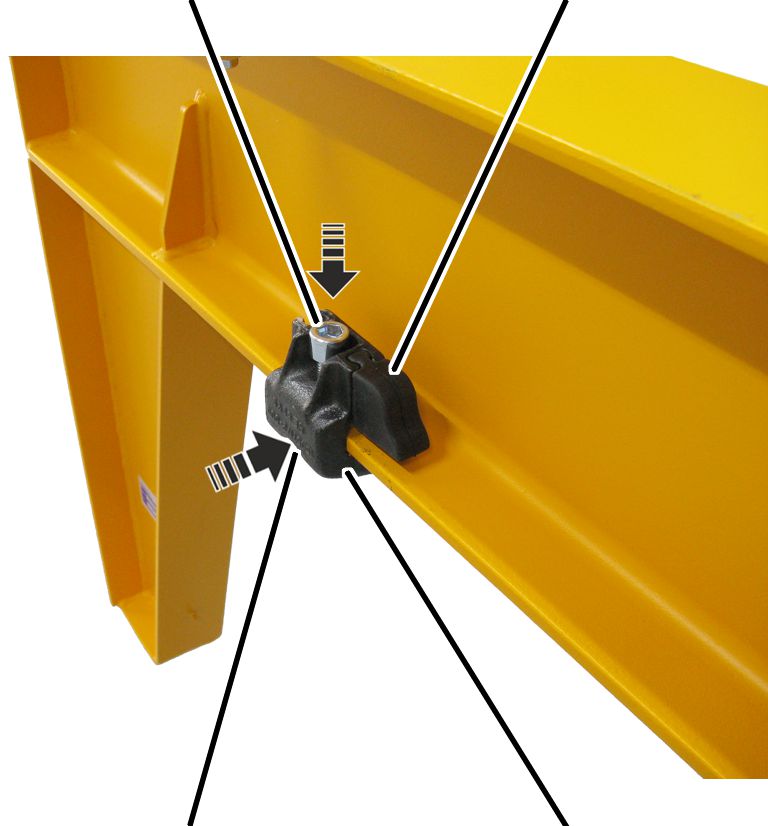
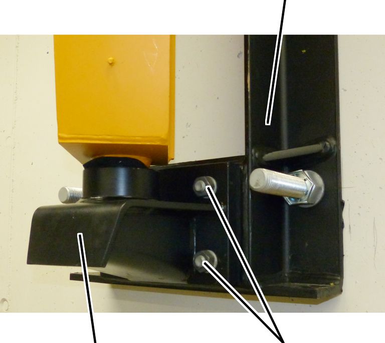
Vertical fillister-head screw |
Rubber buffer |
|
| |
|
Horizontal fillister-head screw |
Clamping buffer |
 Fasten the individual components
(such as trolley, mobile control) to the jib arm and secure them against
slippage, for example, with clamping buffers at suitable points. The individual
components must not roll away unchecked.
Fasten the individual components
(such as trolley, mobile control) to the jib arm and secure them against
slippage, for example, with clamping buffers at suitable points. The individual
components must not roll away unchecked.
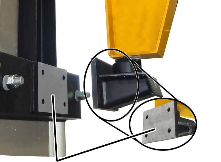
At the upper and lower wall mounts:
|
| |
|
Joint faces |
|
 Thoroughly clean the wall mounts
and the joint faces on the wall mounting (building support, wall bracket,
embracing bracket, weld-on plate) over their entire surface. There should not be
any rust, dirt, scale, paint, lubricant or similar impurities on them.
Thoroughly clean the wall mounts
and the joint faces on the wall mounting (building support, wall bracket,
embracing bracket, weld-on plate) over their entire surface. There should not be
any rust, dirt, scale, paint, lubricant or similar impurities on them.
At first, the jib arm is only bolted on provisionally so that it can then be aligned. To tighten the jib arm fully, see Final tightening of the hexagon head screws on the wall mounts.
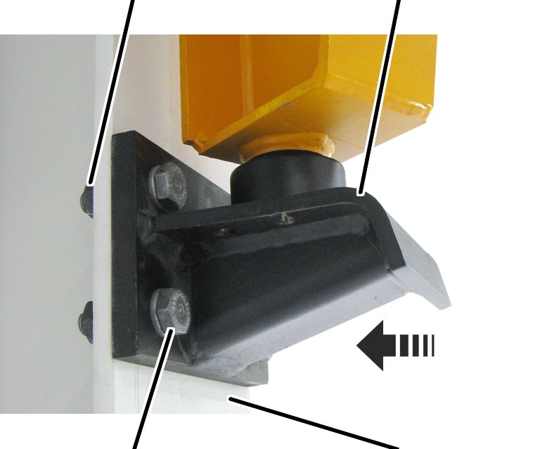
Provisionally bolting on the upper and lower wall mounts:
|
Hexagonal nut and washer |
Wall mounts |
|
| |
|
Hexagon head screw and washer |
Open supporting structure |
Fasten the pre-assembled jib arm
to a suitable hoist.
Observe occupational health and
safety requirements and raise the jib arm.
Place the jib arm in front of
the boreholes.
Screw the wall mounts to the
supporting structure with hexagon head screws and washers.
Provisional tightening torque:
|
Size |
Hexagon head screw |
Number |
Tightening torque |
|
WL 35 |
M16 |
4x |
35 Nm |
|
WL 50 |
M20 |
4x |
60 Nm |
|
WL 60 |
M27 |
4x |
165 Nm |
|
WL 70 |
M27 |
6x |
165 Nm |
With open supporting structures:
attach additional hexagonal nuts and washers at the back.
At first, the jib arm is only bolted on provisionally so that it can then be aligned. To tighten the jib arm fully, see Final tightening of the hexagon head screws on the wall mounts.
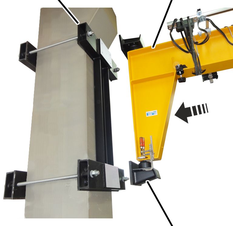
Provisionally bolting on the upper and lower wall mounts:
|
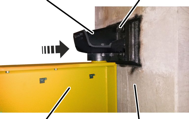
Embracing bracket |
Jib arm | |
|
| ||
|
|
Wall mounts fastened to the jib arm with screw clamps | |
Fasten the pre-assembled jib arm
to a suitable hoist.
Observe occupational health and
safety requirements and raise the jib arm.
Place the jib arm in front of
the boreholes.
Screw the wall mounts to the
supporting structure with hexagon head screws and washers.
Provisional tightening torque:
|
Size |
Hexagon head screw |
Number |
Tightening torque |
|
WL 35 |
M16 |
4x |
35 Nm |
|
WL 50 |
M20 |
4x |
60 Nm |
|
WL 60 |
M27 |
4x |
165 Nm |
|
WL 70 |
M27 |
6x |
165 Nm |
At first, the jib arm is only bolted on provisionally so that it can then be aligned. To tighten the jib arm fully, see Final tightening of the hexagon head screws on the wall mounts.
Provisionally bolting on the upper and lower wall mounts:
|
|
Wall bracket |
|
| |
|
Wall mount |
Hexagon head screws with hexagonal nuts and washers |
Fasten the pre-assembled jib arm
to a suitable hoist.
Observe occupational health and
safety requirements and raise the jib arm.
Place the jib arm in front of
the boreholes.
Screw the wall mounts to the
supporting structure with hexagon head screws, hexagonal nuts and washers.
Provisional tightening torque:
|
Size |
Hexagon head screw |
Number |
Tightening torque |
|
WL 35 |
M16 |
4x |
35 Nm |
|
WL 50 |
M20 |
4x |
60 Nm |
|
WL 60 |
M27 |
4x |
165 Nm |
|
WL 70 |
M27 |
6x |
165 Nm |
At first, the jib arm is only bolted on provisionally so that it can then be aligned. To tighten the jib arm fully, see Final tightening of the hexagon head screws on the wall mounts.
|
|
Danger from falling suspended load! This could result in people being injured or killed. As long as the top weld-on plate is only tack welded, it cannot support the crane. The weld-on plate can break off and the crane could fall, injuring or killing people. Securely support the crane during the entire further installation! |
Provisionally bolting on the upper and lower wall mounts:
|
Wall mount |
Hexagon head screw and washer |
|
| |
|
Jib arm |
Supporting structure |
Fasten the pre-assembled jib arm
to a suitable hoist.
Observe occupational health and
safety requirements and raise the jib arm.
Place the jib arm in front of
the boreholes.
Screw the wall mounts to the
supporting structure with hexagon head screws and washers.
Provisional tightening torque:
|
Size |
Hexagon head screw |
Number |
Tightening torque |
|
WL 35 |
M16 |
4x |
35 Nm |
|
WL 50 |
M20 |
4x |
60 Nm |
|
WL 60 |
M27 |
4x |
165 Nm |
|
WL 70 |
M27 |
6x |
165 Nm |
If the weld-on plates are not plumb:
Install a lining plate between
the anchor plate and wall mount to align.