Only with wall mounting using 3-sided support console
Drilling through the concrete support
|
|
Marking |
|
| |
|
|
Pillar |
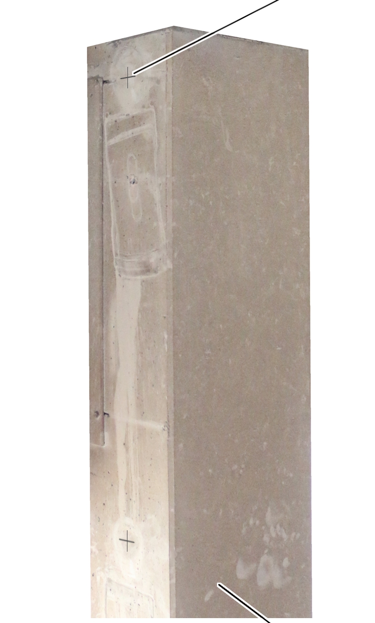
 Compare crane connection
dimensions and transfer to the pillar.
Compare crane connection
dimensions and transfer to the pillar.
Ensure the plumb-vertical position of the slewing axis!
At the upper and lower end of the concrete support:
|
| |
|
Core drill |
Pillar |
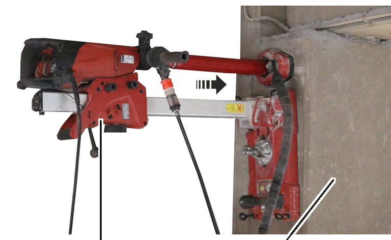
 Drill through the pillar to a
diameter of 62 mm using a water-cooled core drill.
Drill through the pillar to a
diameter of 62 mm using a water-cooled core drill.
Drill the hole completely from one side. Drilling from both sides creates a level through which the tube cannot be inserted in the next step.
Clean hole.
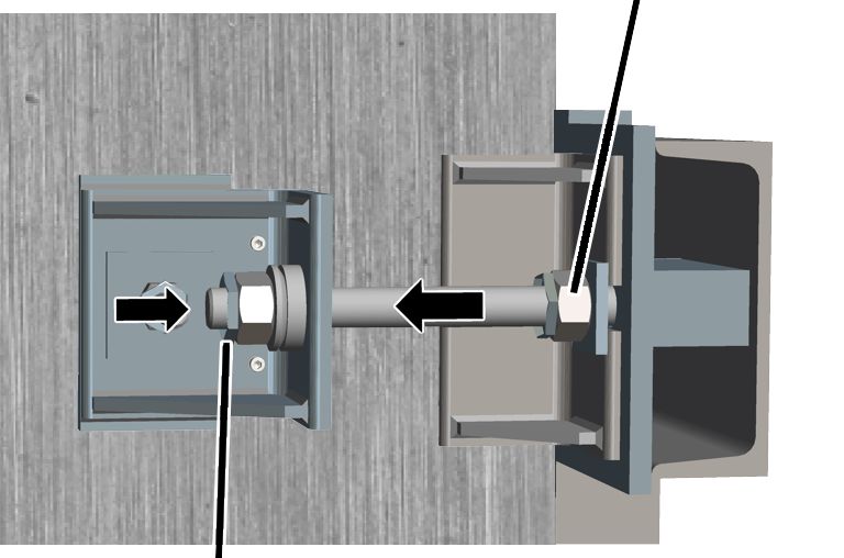
Fitting the mounting blocks
At the upper and lower end of the concrete support:
|
Pipe |
|
|
| |
|
Threaded rod M20 |
|
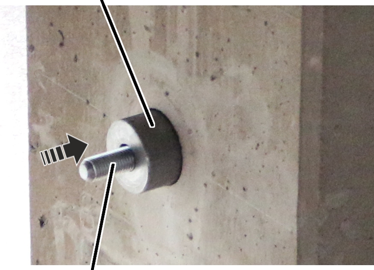
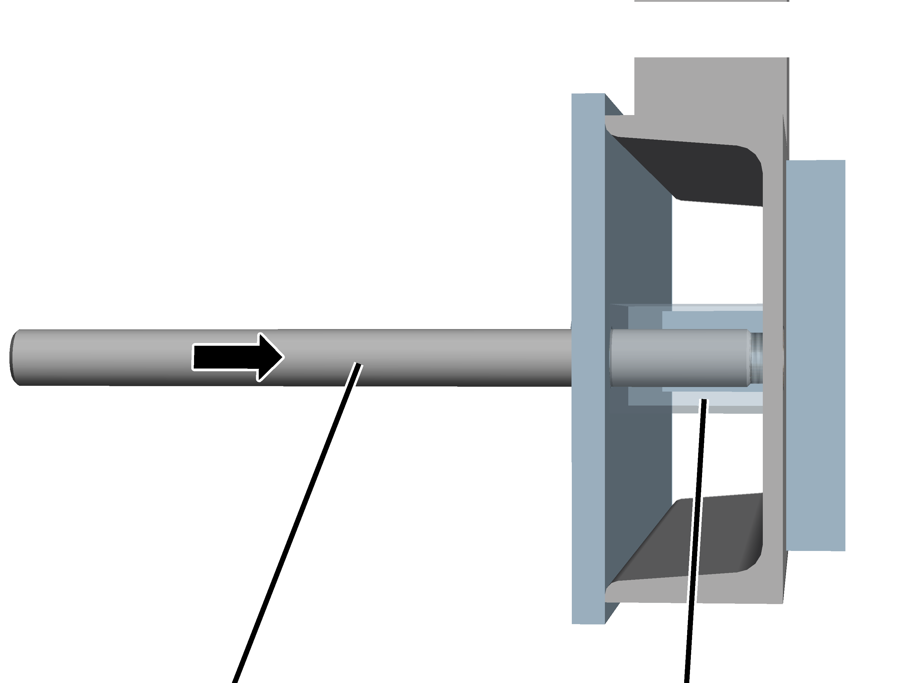
Push the pipe into the upper and
lower hole.
Push threaded rod M20 into the
upper and lower tube.
The threaded rods and tubes must be placed in the hole centrally so that the threaded rod and pipes extend out equally on both sides.
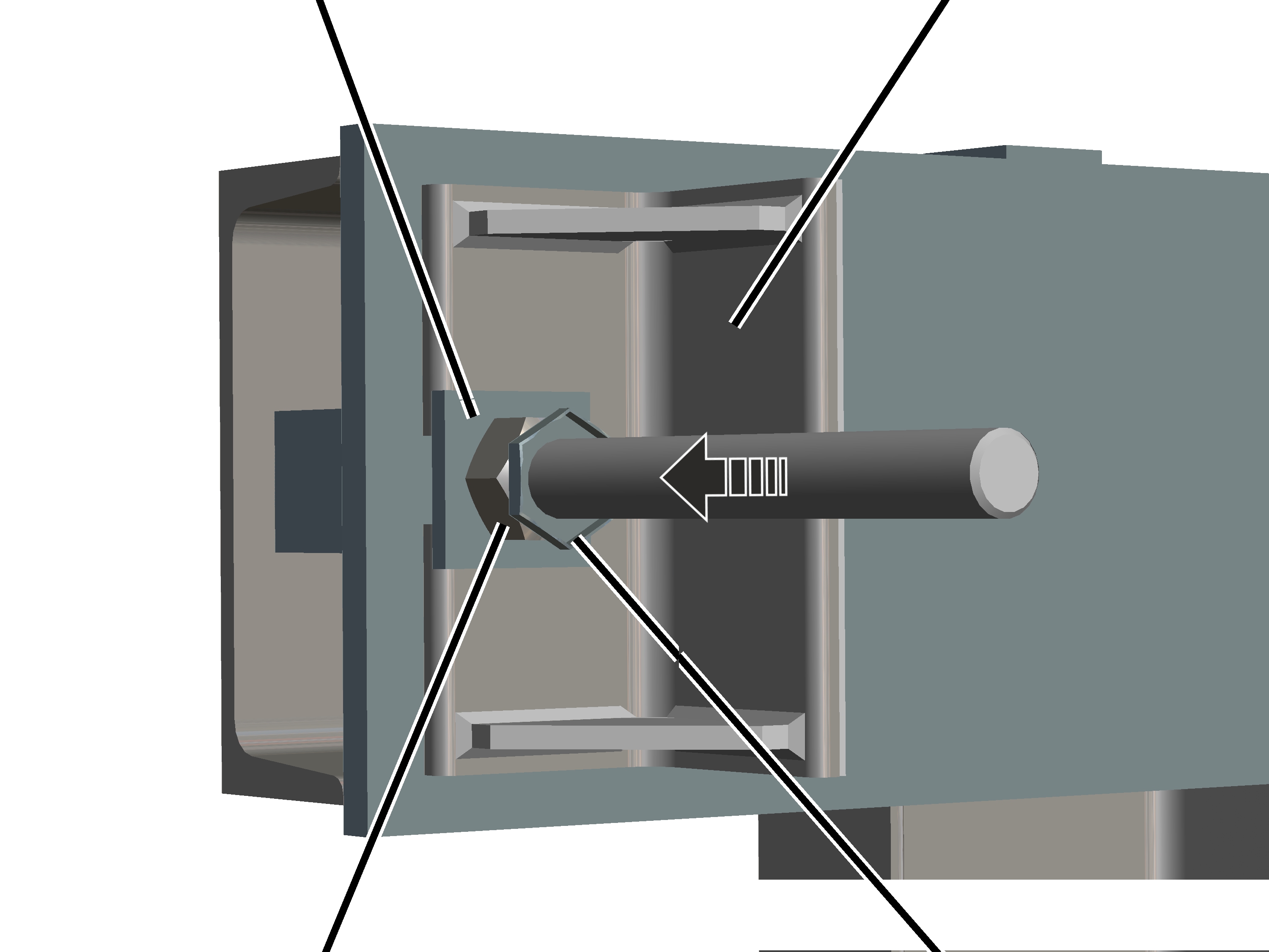
|
Hexagonal nut M20 |
|
|
| |
|
Threaded rod |
Mounting block |
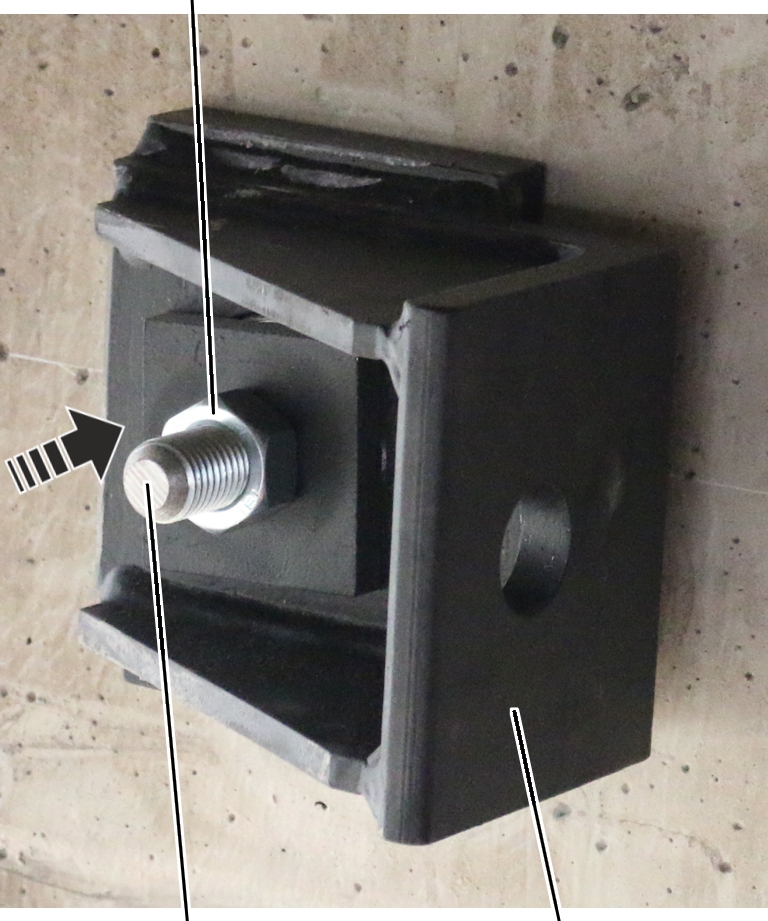
Push mounting blocks (4x) on the
tubes from both sides.
Push the mounting plates (4x) on
the threaded rods.
Secure each mounting plate with
a hexagonal nut M20 (4x).
Preparing the 3-sided support console
|
| |
|
Threaded rod M27 8.8 |
Square end |
Screw threaded rod M27 (4x) into
the support bracket square from behind.
● The threaded rod connects flush with the front side.
|
Shim plate |
Support bracket |
|
| |
|
Hexagonal nut M27 |
Lock nut M27 |
Push the support bracket (4x)
with the open rectangular hole onto the threaded rod.
Secure the support bracket with
the shim plate (4x) and hexagonal nut M27.
Screw lock nut M27 (4x) onto the
threaded rod.
Installing the 3-sided support console
|
|
Danger from tilting and falling down! The 3-sided support console and crossbar are heavy and can kill or injure people if they tilt, become unbalanced, slip or similar during installation. Make sure the 3-sided support console is sufficiently secured during lifting and installation. Observe occupational health and safety requirements. |

Position the support bracket on
the fork of a suitable lift truck.
Observe the occupational health
and safety requirements and lift the support bracket.
Lift the support bracket to the
concrete support.
Push the threaded rods through
the holes on the mounting blocks.
If the mounting blocks do not rest on the limbs of the side support bracket:
|
|
Mounting block |
|
| |
|
Lining plate |
Cylinder head bolt with spring lock washer |
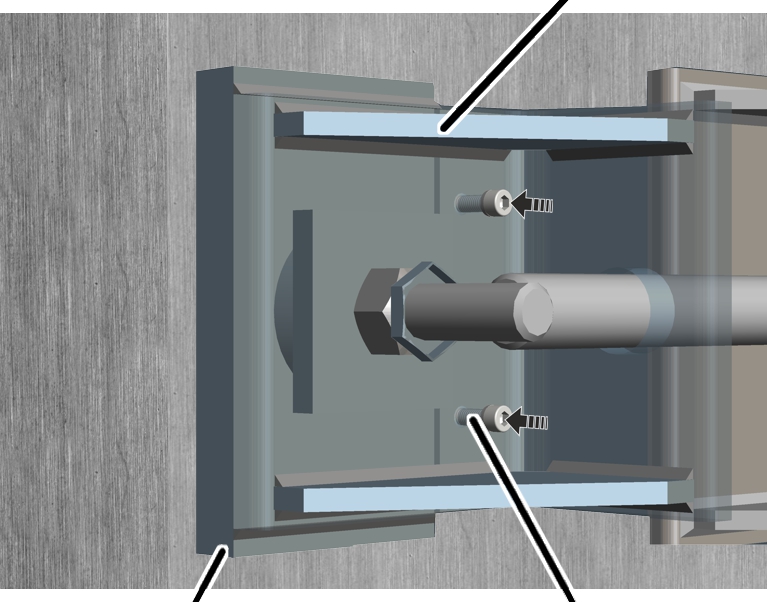
Install on each mounting block a
lining plate with 2 cylinder head bolts and spring lock washer as a building
support for the mounting block.
|
Hexagonal nut M27 |
Ball socket |
|
| |
|
|
Spherical washer |
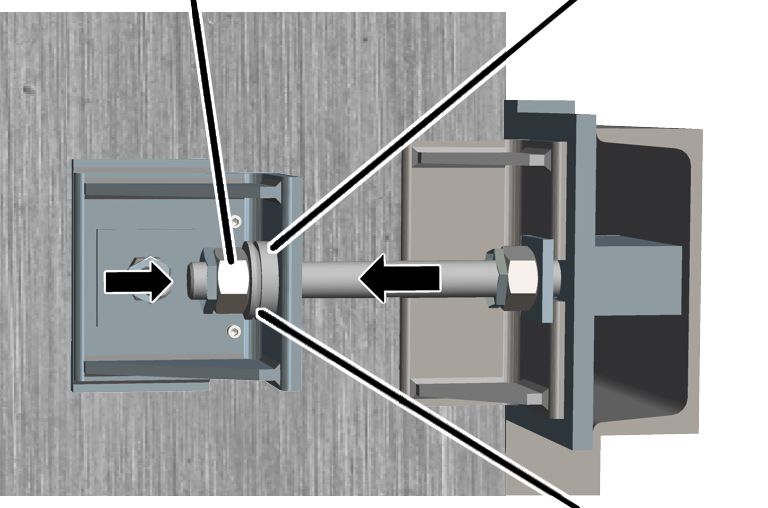
Push the ball socket (4x) and
spherical washer (4x) onto the threaded rod.
Screw the hexagonal nut (4x)
onto the threaded rod.
Position the support bracket
vertically.
Tighten hexagonal nut M27.
380 Nm.
|
|
Hexagonal nut M27 |
|
| |
|
Lock nut |
|
Tighten hexagonal nuts M27.
900 Nm.
Screw on the lock nut.