Only with a slewing drive
The slewing gear unit with slewing drive is installed AFTER aligning the jib arm.
|
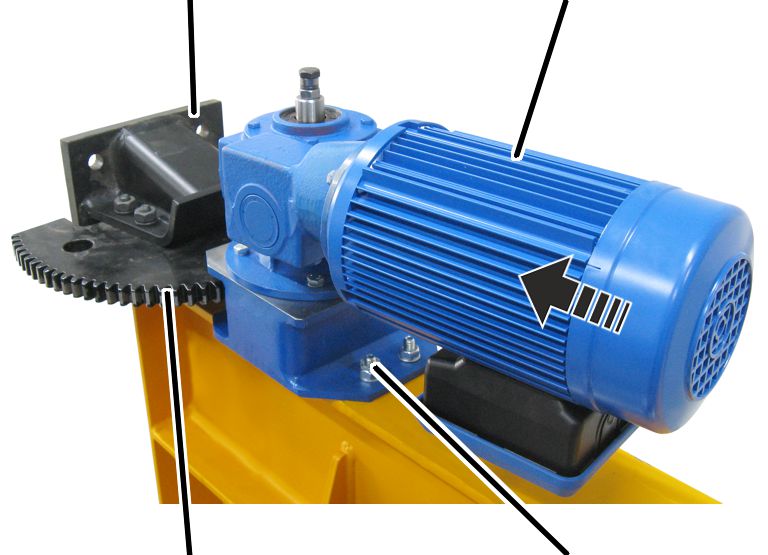
High-tensile bolts with washers and hexagonal nuts |
Wall mount |
|
| |
|
Toothed segment |
|
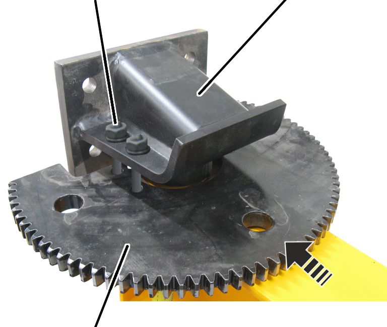
 Screw the toothed segment and
wall mounts together with the corresponding high-tensile bolts (4x), washers
(8x) and hexagonal nuts (4x) using the required tightening torque.
Screw the toothed segment and
wall mounts together with the corresponding high-tensile bolts (4x), washers
(8x) and hexagonal nuts (4x) using the required tightening torque.
|
Size |
High-tensile bolt |
Tightening torque |
|
WL 35/WL 50 |
M12x60 |
120 Nm |
|
WL 60/WL 70 |
M16x70 |
284 Nm |
Installing the slewing drive on the slewing gear unit
|
| |
|
Slewing drive |
Slewing gear unit |
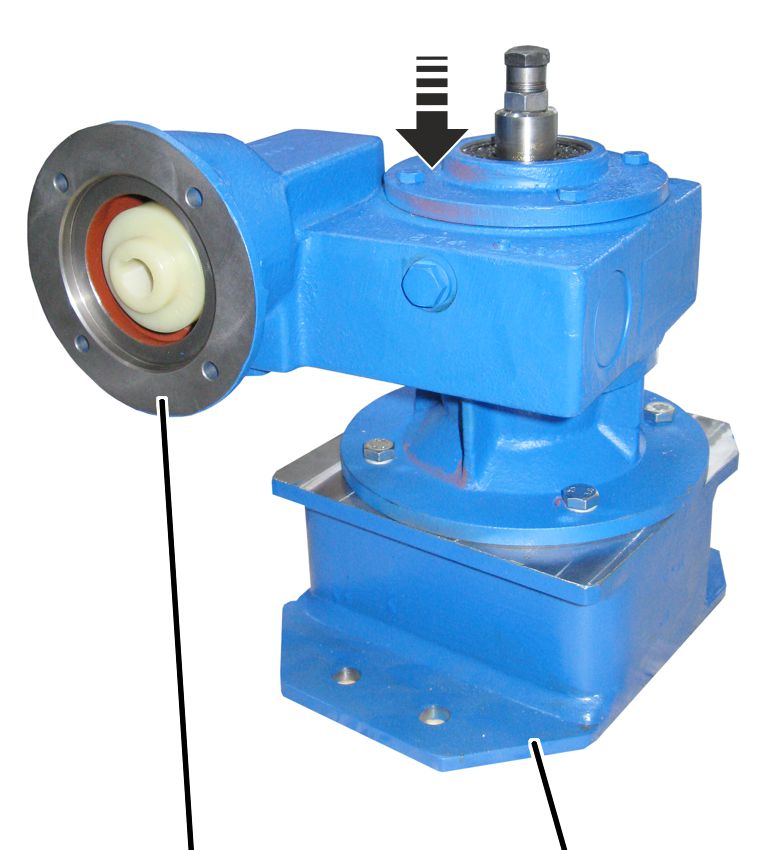
Place the slewing drive on the
slewing gear unit.
For WL 35, WL 60 and
WL 70 only: Tighten the slewing gear with hexagon head screws (4x) and
washers (4x).
|
Size |
Hexagon head screw |
Tightening torque |
|
WL 35 |
M8x20 |
8 Nm |
|
WL 60/WL 70 |
M12x30 |
35 Nm |
For WL 50 only: Tighten the
slewing gear with rib screws M10x25 (4x). 35 Nm.
The figures show a coupler plug with a sprocket. This can vary depending on the type of motor. The installation does not differ significantly.
|
Slewing motor |
Sprocket |
|
| |
|
|
Slewing gear |
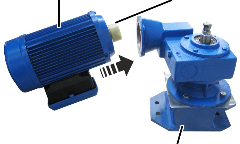
 Place the sprocket on the output shaft of the slewing motor.
Secure the sprocket using a stud.
Place the slewing motor in the slewing gear.
Screw the slewing motor in place using hexagon head screws M6x20
(4x). 10 Nm.
Installing the slewing gear unit on the jib arm
|
Slewing gear unit |
Tensioner sleeves |
|
| |
Drive the tensioner sleeves about halfway into the holes on the
slewing gear unit.
|
Wall mount |
Slewing motor |
|
| |
|
Toothed segment |
Slewing gear unit |
Place the slewing drive on the
toothed segment.
Bolt the slewing gear unit to
the jib arm with tensioner sleeves (4x), hexagon head screws (4x), washers (8x)
and hexagonal nuts (4x). 45 Nm.
|
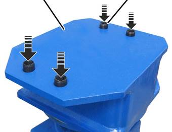
Slewing gear unit |
Lock nuts |
|
| |
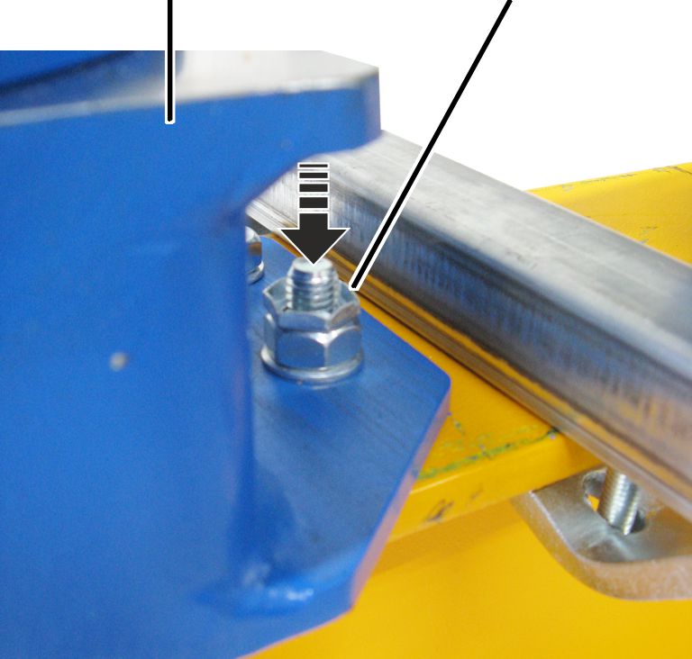
 Secure the screw connection with lock nuts (4x).
Inserting and connecting the connection cables in the connector housing
|
Bottom section of connector housing |
Slewing motor |
|
| |
|
Cable bushing |
Connector |
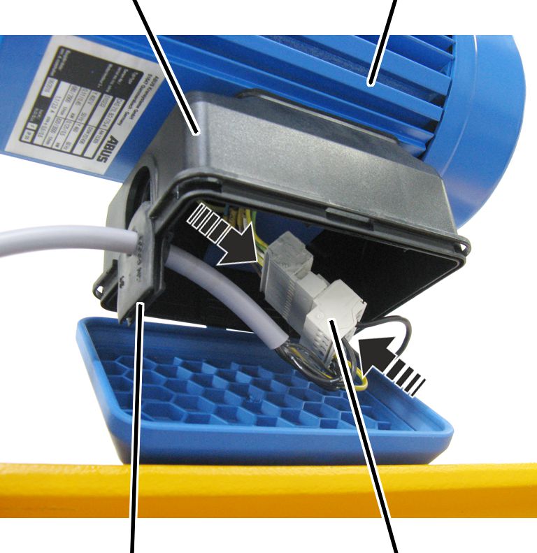
Open the housing cover.
Push the cable bushing into the housing and plug in the
connector.
Closing the connector housing
|
| |
|
Housing cover |
Bottom section of connector housing |
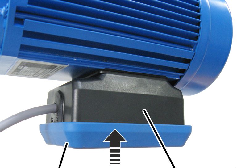
Place the housing cover on the bottom section of the connector
housing.