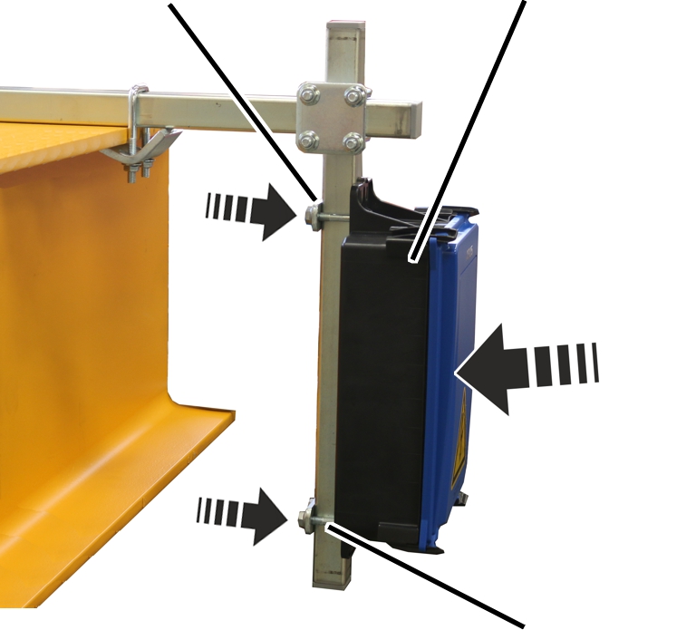
Clamping claws
Vertical square tube
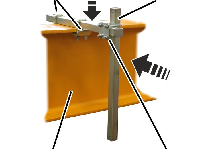
Jib arm
Pipe clamp
A fuse housing is now installed on a number of jib cranes. The scope of delivery indicates whether this housing needs to be installed.
Three fuses are placed in the housing, which are used to fuse the crane.
|
Clamping claws |
Vertical square tube |
|
| |
|
Jib arm |
Pipe clamp |
 Lay the horizontal square tube
onto the jib arm so that the trolley power supply cable carrier does not collide
with the housing.
Lay the horizontal square tube
onto the jib arm so that the trolley power supply cable carrier does not collide
with the housing.
Screw the horizontal square tube
with clamping claws (2x) on the jib arm. 23 Nm.
Push the vertical square tube
with a pipe clamp onto the horizontal square tube.
 Screw the pipe clamp tight.
23 Nm.
Screw the pipe clamp tight.
23 Nm.
|
Plate |
Housing |
|
| |
|
|
Threaded bracket |
Push the threaded bracket (2x)
through the lugs on the housing.
Push the housing, together with
the threaded brackets, onto the vertical square tube from the front.
Place the plates onto the
threaded bracket from the rear.
Screw the plates in place using
rib nuts M8. 23 Nm.
|
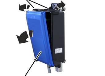
Clip fasteners |
|
|
| |
|
Cover |
|
Open the clasps on one side of the housing.
Flip the cover out
laterally.
● The cover releases automatically from the clasps on the other side when flipped open.
|
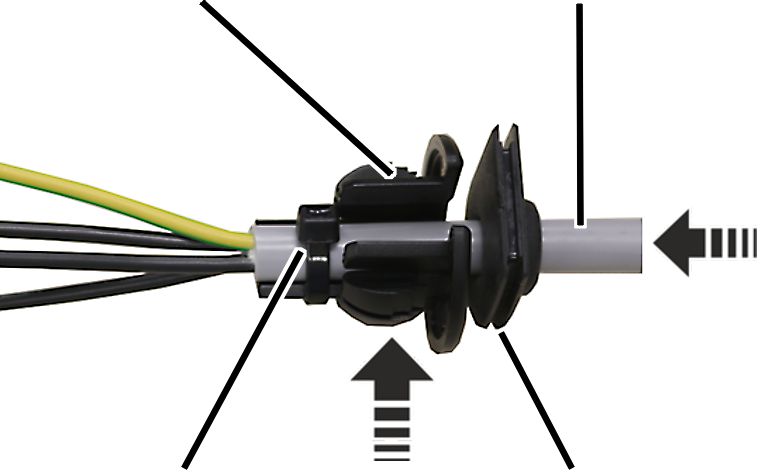
Cable bushing |
Connection cable |
|
| |
|
Cable ties |
Cable bushing (as seal) |
Strip approximately 20 cm
sheathing from the connection cables.
Push the connection cable
through the suitable cable bushing (seal).
The housing contains suitable cable bushings for thick or thin round cables and flat cables.
Push the connection cable
through the cable bushing (strain relief) and fasten it with cable clips.
|
|
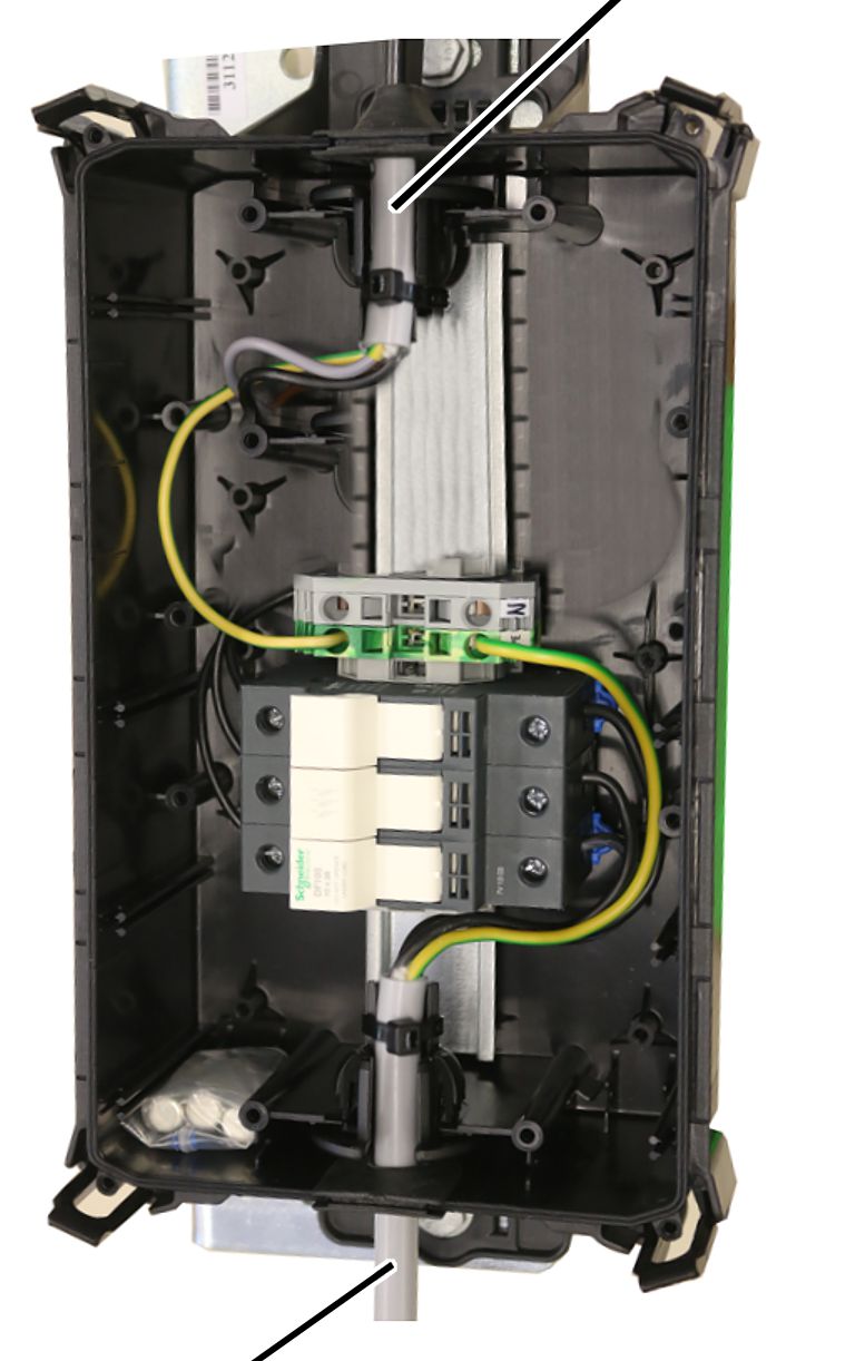
Trolley power supply |
|
| |
|
Mains power supply |
|
Push the connection cable with
the two cable bushings into the housing.
─ Push the mains power supply on the side with the fuse holder into the housing.
─ Push the trolley power supply on the side with the terminals for the neutral and protective conductor into the housing.
Insert the rubber lips of the
cable bushing (seal) so that they lay flat against the housing both inside and
outside.
Insert the cable bushing (strain
relief) into the housing as shown in the figure.
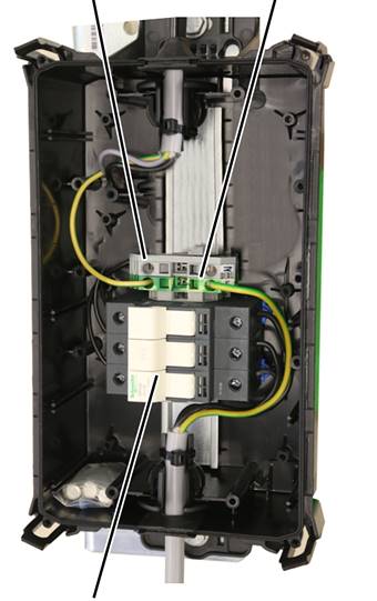
|
Terminal for neutral conductor |
Terminal for protective conductor |
|
| |
|
Fuse isolating link |
|
Attach the connection cable from
the mains power supply to the fuse isolating link.
Attach the connection cable to
the trolley power supply on the fuse isolating link.
Connect both protective
conductors to the terminal for protective conductors.
If necessary: connect both
neutral conductors to the terminal for neutral conductors.
Place the cover on the housing so it lies
straight.
Do not first latch and tilt the cover on one side.
Use light pressure to latch the
cover on all four clasps of the housing.