Mounting plate
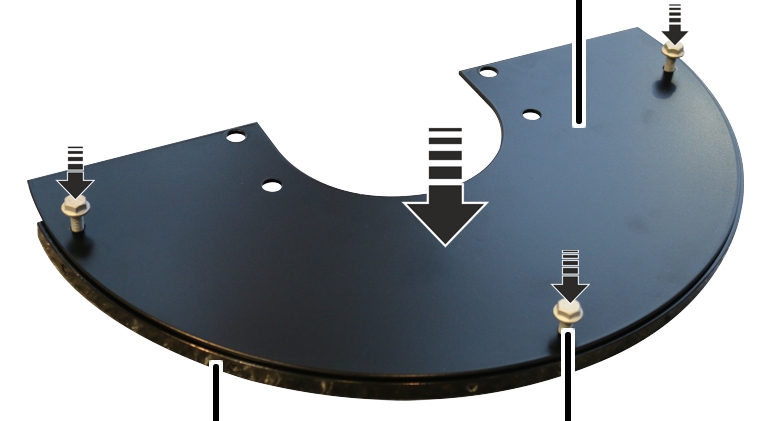
Gusset plate
Rib screw M8x25
Depending on the crane design, an electrical slew switch-off is now installed which limits the slewing range of the crane electrically.
The electric slew switch-off switch consists of two or four limit switches, which are attached to the jib bracket using a bracket, as well as flexible plastic switching lugs, which are fixed to the switch rail segment with a special tape fastener.
Depending on the control and switch-off (braking function and shut-down), a different number of limit switches must be installed at various positions.
For braking function or shut-down:
First mounting plate (with two limit switches), installed at the top of the vertical square tube of the mount on the jib bracket.
|
Switch-off |
Slewing direction |
Position of the limit switch |
|
Shut-down |
Right |
Top |
|
Braking function |
Right |
Bottom |
Second mounting plate (with two limit switches), installed at the top of the vertical square tube of the mount on the jib bracket.
|
Switch-off |
Slewing direction |
Position of the limit switch |
|
Shut-down |
Left |
Top |
|
Braking function |
Left |
Bottom |
For braking function or shut-down:
First mounting plate (with two limit switches), installed at the top of the vertical square tube of the mount on the jib bracket.
|
Switch-off |
Slewing direction |
Position of the limit switch |
|
Braking function |
Left and right |
Bottom |
|
Shut-down |
Right |
Top |
Second mounting plate (with one limit switch), installed at the top of the vertical square tube of the mount on the jib bracket.
|
Switch-off |
Slewing direction |
Position of the limit switch |
|
Shut-down |
Left |
Top |
If the switch rail segment has not yet been assembled, continue here. Otherwise, skip this section.
|
|
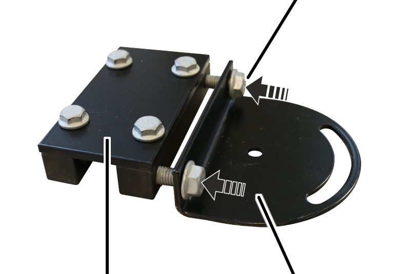
Mounting plate |
|
| |
|
Gusset plate |
Rib screw M8x25 |
 Bolt the mounting plate to the gusset plate with M8x25 rib screws
(3x). 35 Nm.
Bolt the mounting plate to the gusset plate with M8x25 rib screws
(3x). 35 Nm.
|
Mounting plate |
|
|
| |
|
Rib screw M6x16 |
Web plate |
 Bolt the gusset plate to the web plate with M6x16 (6x) rib screws.
16 Nm.
Bolt the gusset plate to the web plate with M6x16 (6x) rib screws.
16 Nm.
With wall mount size WL60 or WL70, the switch rail segment must be jacked up so that it does not press against the weld seam of the wall mount. To do this, each of the holes in the wall mount gets a spacer strip placed on it, which is then bolted together with the switch rail segment.
|
Spacer strip |
|
|
| |
|
Wall mount |
Spacer strip |
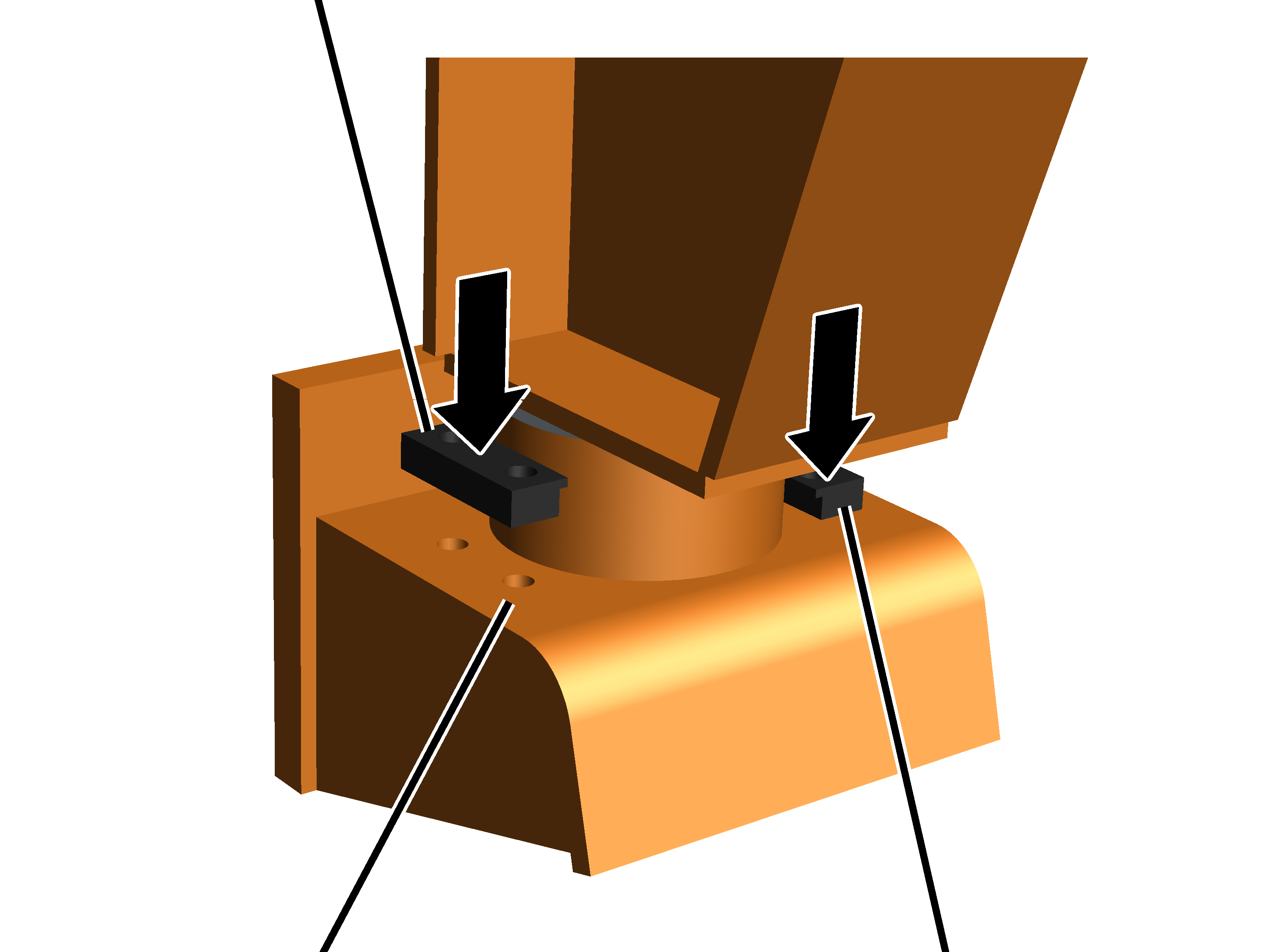
Place the spacer strips (2x) on the holes in the wall mount.
The holes in the wall mount and the holes in the spacer strips must match exactly.
|
|
Wall mount |
|
| |
|
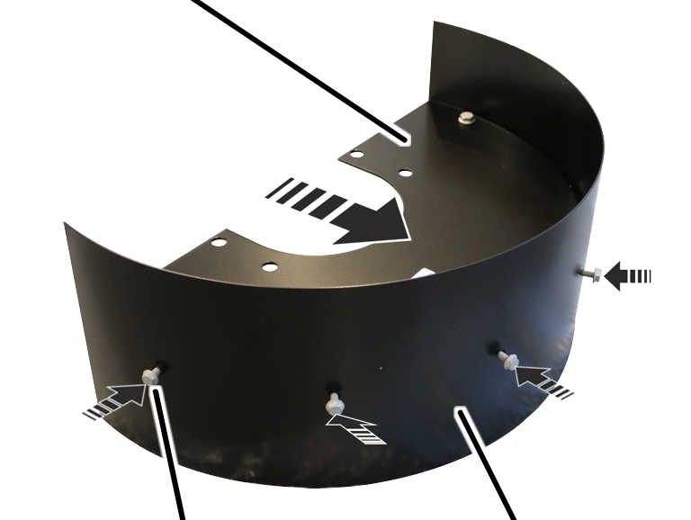
Rib screw |
Switch rail segment |
Bolt the switch rail segment to the wall mount using rib screws (4x)
and rib nuts (4x).
|
Size |
Screw |
Tightening torque |
|
WL35/WL50 |
M12x40 |
100 Nm |
|
WL60/WL70 |
M16x60 |
250 Nm |
|
|
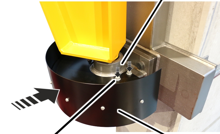
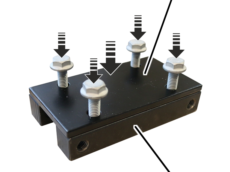
Metal plate |
|
| |
|
|
Clamping piece |
Bolt the plate to the clamping pieces (2x) with M8x25 rib screws
(4x). 35 Nm.
|
|
Rib screw M10x20 |
|
| |
|
Clamping piece |
Alignment segment |
Bolt the alignment segment to the clamping piece using M10x20 rib
screws (2x). 65 Nm.
|
Alignment segment |
Square tube |
|
| |
|
|
Rib screw M8x40 |
Bolt the square tube to the alignment segment using M8x40 rib screws
(2x) and M8 rib nuts (2x). 35 Nm.
|
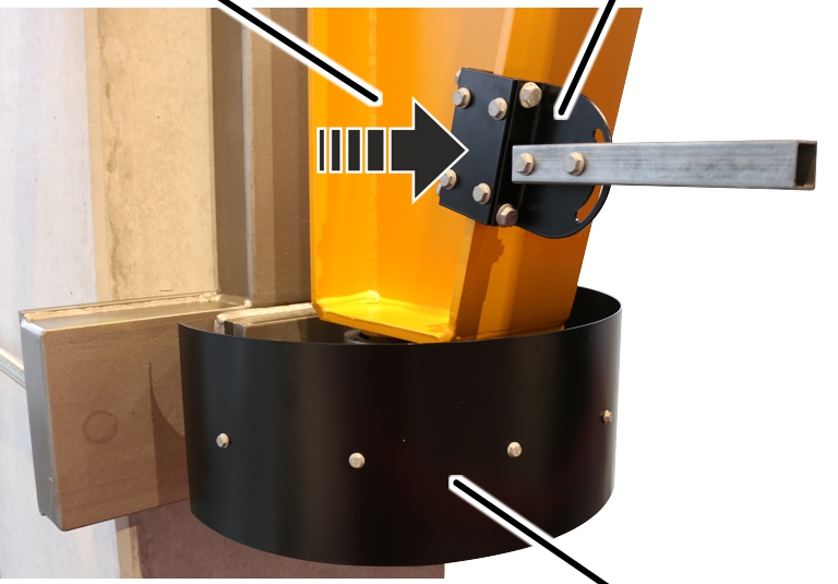
Jib bracket |
Alignment segment |
|
| |
|
|
Switch rail segment |
Bolt the clamping piece with alignment segment and square tube to one
side of the jib bracket using M10x40 rib screws (2x). 65 Nm.
Align the square tube horizontally.
|
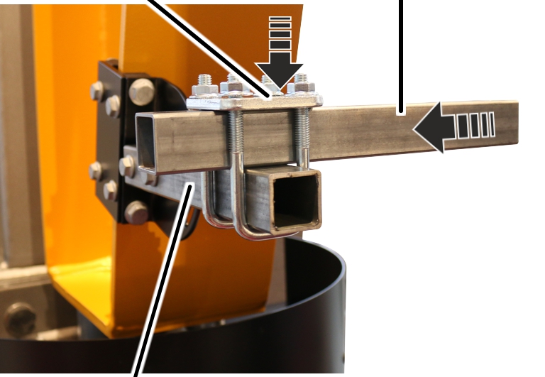
Pipe clamp |
Square tube |
|
| |
|
Square tube |
|
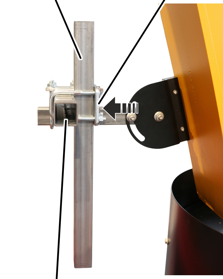
Initially only loosely bolt the second square tube to the horizontal
square tube using a pipe clamp and M8 rib nuts offset by 90°.
The limit switches still need to be aligned later. Therefore, the square tube should not yet be bolted tight with tightening torque.
|
Vertical square tube |
Pipe clamp |
|
| |
|
Square tube |
|
Bolt the vertical square tube loosely to the previously mounted
horizontal square tube from the inside using a pipe clamp and M8 rib nuts.
The limit switches still need to be aligned later. Therefore, the square tube should not yet be bolted tight with tightening torque.
|
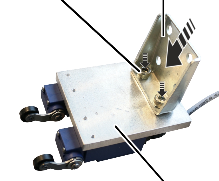
Fillister-head screw M8x10 |
Bracket |
|
| |
|
|
Connection plate with limit switches |
Bolt the angle (2x) to the connection plate (2x) using M8x10
fillister-head screws (4x). 35 Nm.
|
|
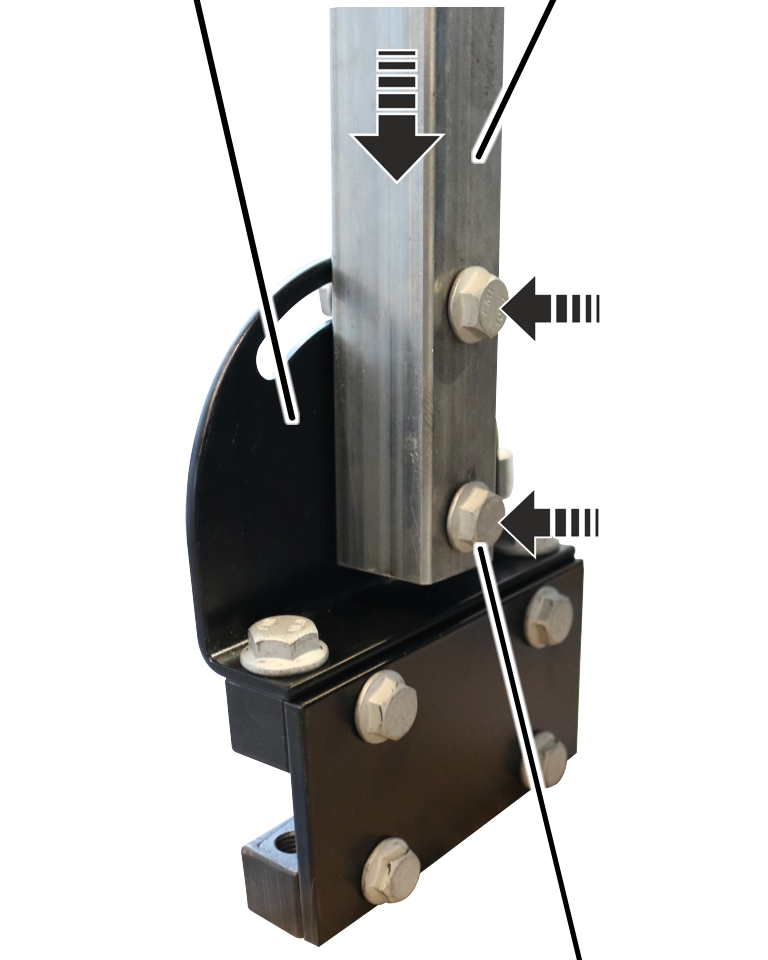
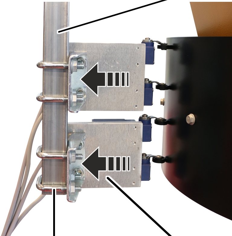
Vertical square tube |
|
| |
|
Threaded bracket with rib nuts |
Connection plate with limit switch and angle |
Bolt the angle (2x) to the vertical square tube using threaded
brackets (4x) and M8 rib nuts (8x). 35 Nm.
The limit switches must be installed on the same side!
|
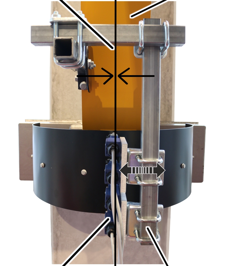
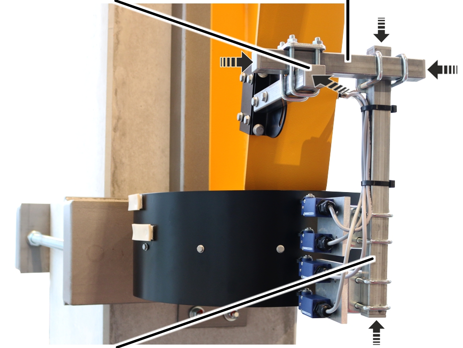
Centre of the jib bracket |
Jib bracket |
|
| |
|
Limit switch |
Vertical square tube |
Slew the jib arm until the jib bracket is centred in relation to the
switch rail segment.
Align the vertical and horizontal square tube so that the limit
switches point towards the centre of the jib bracket and touch the switch rail
segment.
The rollers of the limit switch must run along the switch rail segment.
Tighten the pipe clamps. 15 Nm.
|
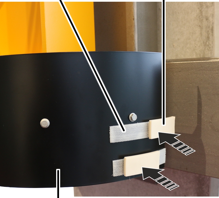
Tape fastener |
Control cam |
|
| |
|
Switch rail segment |
|
Mark the switching point and swivel the jib arm to the side.
Glue the tape fastener to the switch rail segment.
The limit switch must run along the centre of the control cam.
Press the switching lugs onto the tape fastener so that the limit
switch is activated at the respective switching point.
Repeat the procedure for all switching points.
|
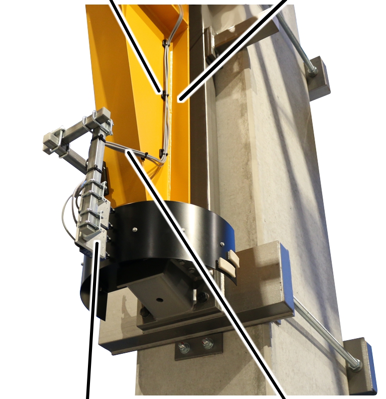
Cable fasteners |
Jib bracket |
|
| |
|
Connection plate with limit switches |
Connection cable |
Lay the connection cable from the limit switch to the control.
Fasten the connection cables to the cable fasteners on the jib
bracket with cable ties.
Guide the connection cable into the control and connect it. See the
wiring diagram.
Check the electrical slew switch-off.
|
Ribbed end cap |
Square tube |
|
| |
|
Square tube |
|
If the square tubes protrude too far:
Shorten the square tubes.
Press the ribbed end caps into the ends of the square tubes.