Only with a control in the panel
This section only applies when the jib crane control is placed in a panel.
Installing the bracket
─ The panel is usually installed so that it is on the same side as the trolley power supply, and points outwards and downwards.
─ If necessary, the panel can also be installed on the opposite side.
─ If necessary, the panel can also be installed pointing upwards. Alternatively, the panel can also be installed pointing upwards and inwards.
The figures show the installation of a suspended panel on the same side as the trolley power supply. The installation of a panel pointing upwards, or a panel suspended on the other side, is, essentially, no different.
|
Square tube |
Clamping claws |
|
| |
|
Bracket |
Pipe clamp |
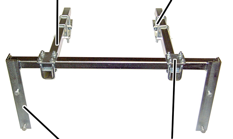
 Place pipe clamps (2x) on the
bracket loosely.
Place pipe clamps (2x) on the
bracket loosely.
Insert square tube (2x) in the
pipe clamps. Screw the rib nuts on the pipe clamps. 23 Nm.
Push clamping claws (4x) loosely
onto the square tube.
|
Bracket |
|
|
| |
|
Clamping claw |
Jib arm |
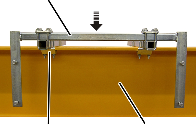
Place the bracket with the
clamping claws onto the jib arm.
Push the clamping claws (4x)
onto the jib arm and screw them tight. 23 Nm.
Installing the panel
|
| |
|
|
Panel |
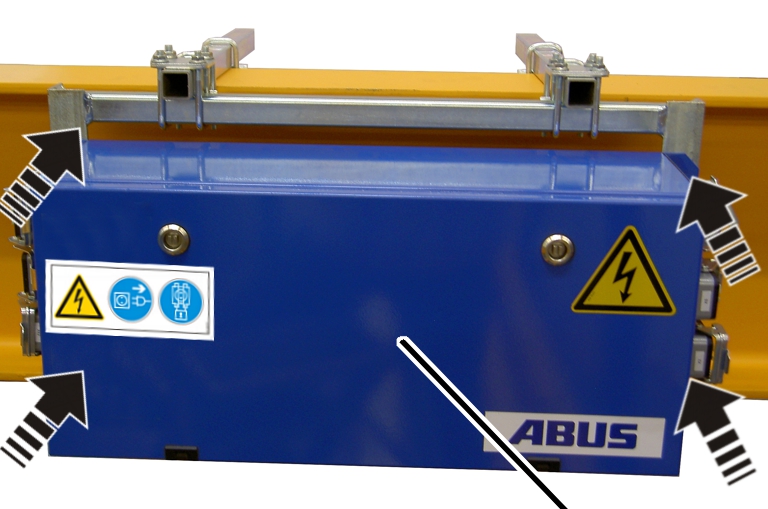
Place the panel on the
bracket.
Screw the panel in place using
rib screws M8x25. 23 Nm.
Connecting the connection cables
Connection cables with connector:
|
|
Connector |
|
| |
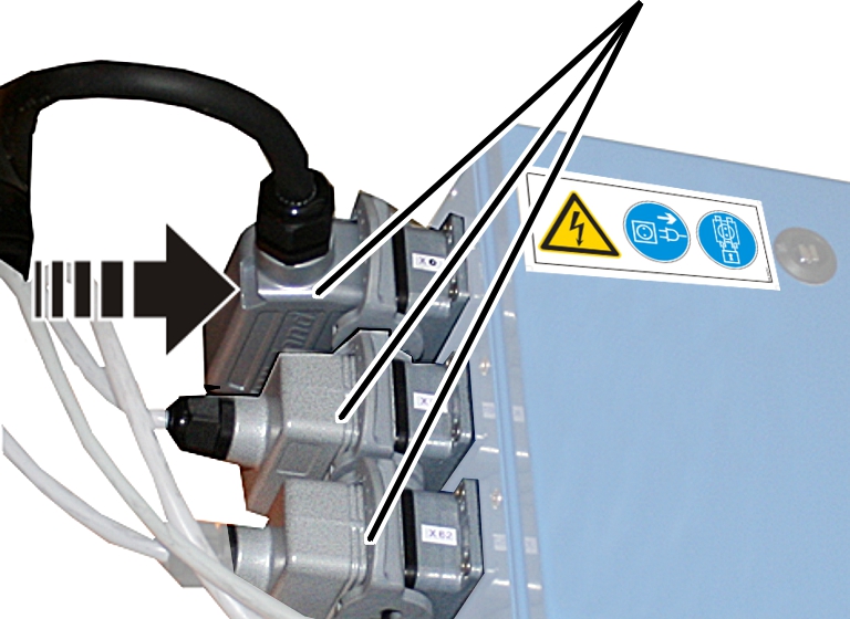
Plug the connector onto the
panel. See the wiring diagram.
Allow the socket retaining clips
to click into place.
Connection cables without a connector:
|
| |
|
Cable fitting |
Round cable |
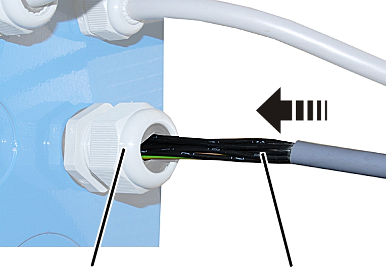
If necessary: break off the
perforated section in the panel.
Install the cable fitting.
Push the connection cable into
the cable fitting.
Screw the cable fitting together
until the cable is securely and tightly fixed in place.
Connect the connection cables in
the panel. See the wiring diagram.