Front
mounting bracket
at a distance of 200 mm
from the jib
tip
Rear mounting bracket above the centre of the jib bracket
Remaining mounting brackets distributed evenly
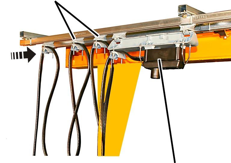
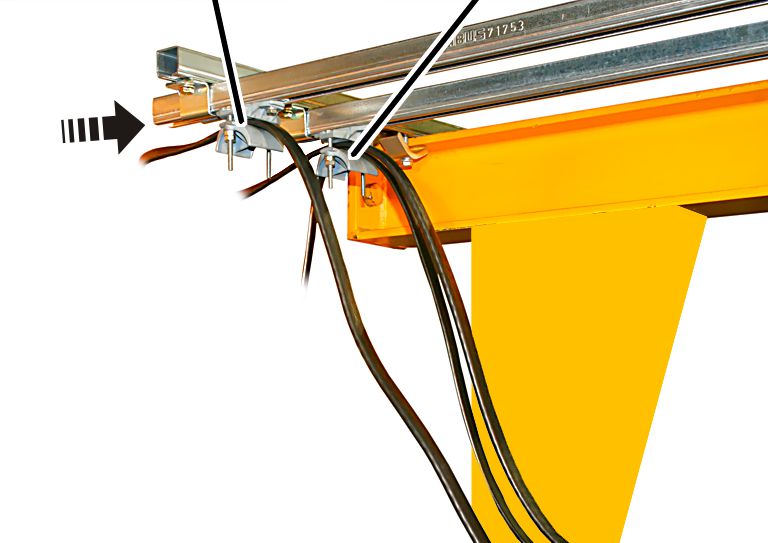
The trolley power supply and the mobile control (option) are now installed on the jib arm.
The direction in which the trolley power supply is installed (on the left or right side of the jib arm) is specified in the planning documents.
The figures show installation of the trolley power supply and mobile control on the same side. The installation of the trolley power supply and mobile control on the opposite side is, essentially, no different.
|
Front
mounting bracket |
Rear mounting bracket above the centre of the jib bracket |
|
| |
|
|
Remaining mounting brackets distributed evenly |
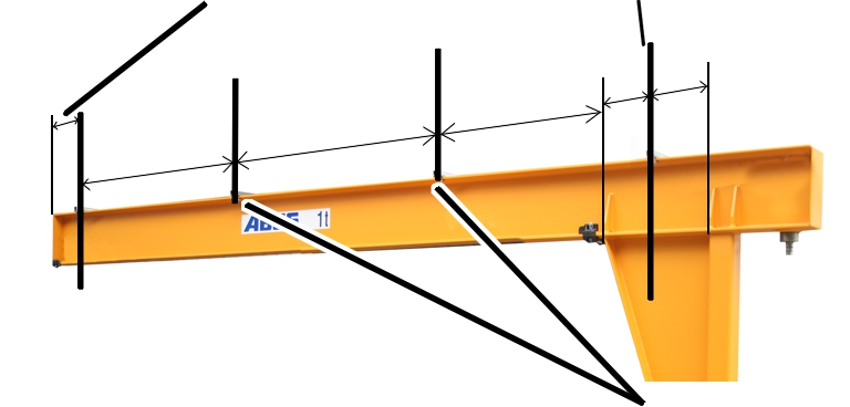
 Place the first and last mounting
bracket in position on the jib arm:
Place the first and last mounting
bracket in position on the jib arm:
─ On the jib tip: place the front mounting bracket in position at a distance of 200 mm in front of the jib tip.
─ At the jib arm start point: bring the rear mounting bracket into position roughly centred over the jib bracket.
 Place all other mounting
brackets in position evenly spaced between them.
Place all other mounting
brackets in position evenly spaced between them.
For a pendant control on the trolley only:
|
|
Mounting bracket |
|
| |
|
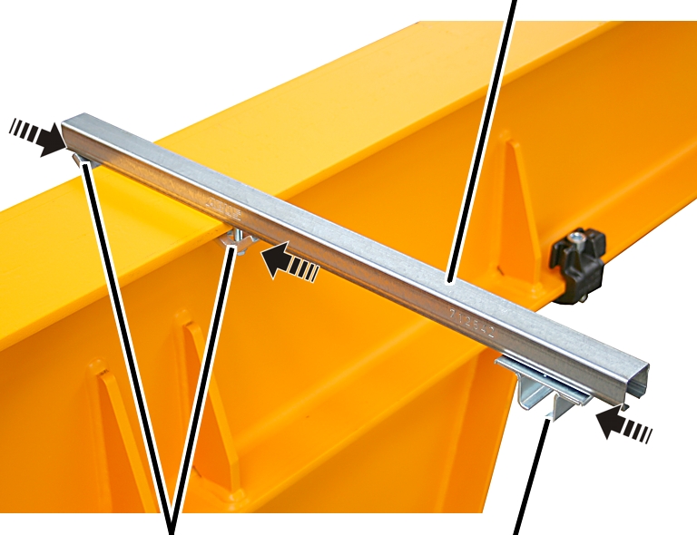
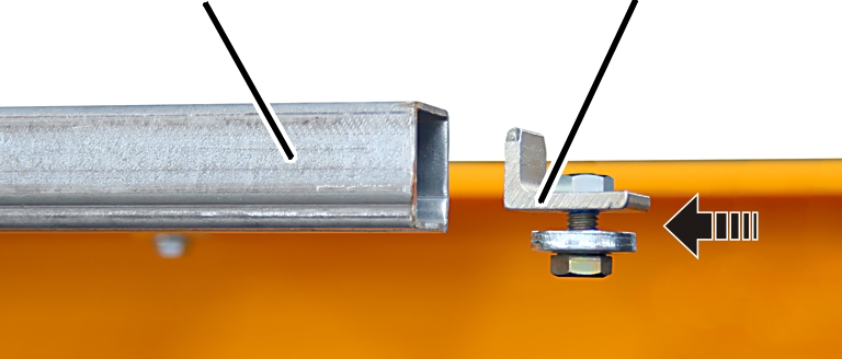
Clamping claws |
Rail mount |
Insert the rail mount (1x)
into the mounting bracket.
|
|
Mounting bracket |
|
| |
|
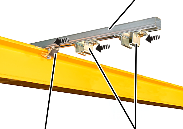
Clamping claw |
Rail mount |
Insert the rail mount (2x)
into the mounting bracket.
Distance between two rail mounts: 120 mm to 150 mm.
|
| |
|
|
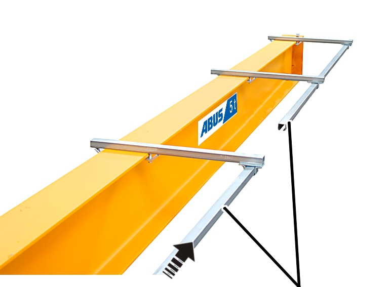
C-rails |
Insert C-rails for the
trolley power supply into the rail mount.
The C-rails run parallel to the jib arm. The C-rails may protrude a little in front of the first mounting bracket and behind the last mounting bracket.
Only with mobile control:
insert the C-rails for the mobile control parallel to it as well.
Tighten all rail mounts.
23 Nm.
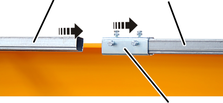
Connect two C-rails to each other:
|
C-rail |
C-rail |
|
| |
|
|
Rail connector |
Push the rail connector
onto the C-rail.
Push the second C-rail
into the rail connector.
Tighten the hexagon head
screws M6x12 on all three sides so that there is no offset between the inner
surfaces of the C-rails.
The smaller the offset between the C-rails is, the better the trolley power supply or the mobile control will move.
Screw on hexagonal nuts
M6. 4 Nm.
On the jib tip:
|
C-rail |
End stopper |
|
| |
Push the end stopper into
the C-rail for the trolley power supply.
Tighten the end stopper
with a hexagon head screw M8x20. 23 Nm.
Only with mobile control:
push the end stopper into the C-rail for the mobile control as well, and tighten
it.
The planning documents specify into which of the C-rails the trolley power supply is inserted, and into which the mobile control is inserted.
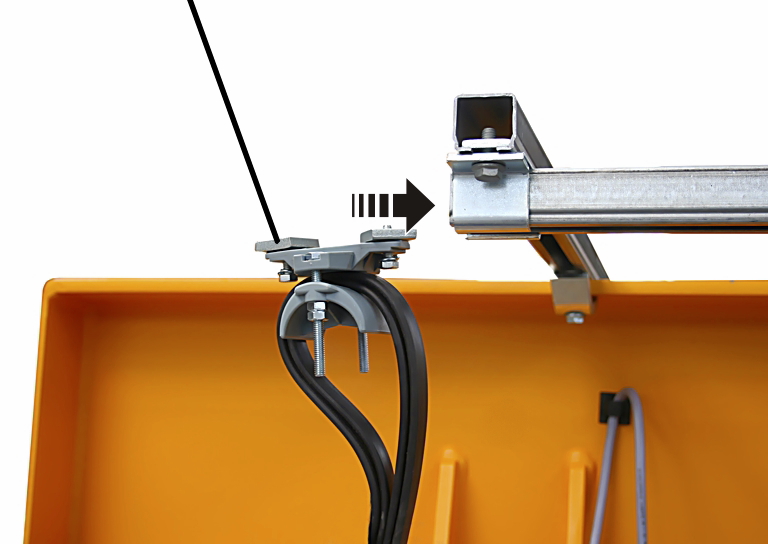
At jib arm start point:
|
Cable carrier with plastic castors |
Cable carrier with metal castors |
|
| |
Push the cable carrier
with metal castors into the C-rail first.
Then push the cable
carrier with plastic castors into the C-rail in the correct order.
|
End terminal |
|
|
| |
Last of
all, push the end terminal into the C-rail.
Push the end terminal in
until it reaches approx. 50 mm before the end of the C-rail.
Screw the end terminal in
place. 23 Nm.
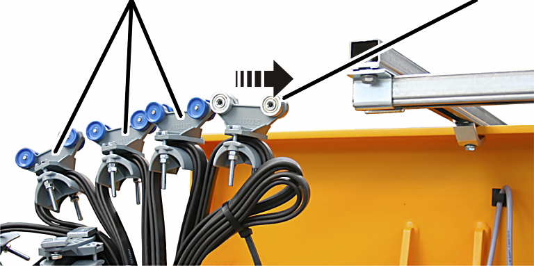
At jib arm start point:
|
Cable carrier |
|
|
| |
|
|
Control trolley |
From the jib arm start
point: first, push the control trolley into the C-rail.
Then push the cable
carriers into the C-rail in the correct order.
|
End terminal of the trolley power supply | |
|
| |
|
|
|
Last of all, push the end
terminal (2x) into the C-rail.
Push the end terminals
until they reach approx. 50 mm before the end of the C-rail.
Screw the end terminal in
place. 23 Nm.