Only with slewing stops on the slewing crane with a cylindrical pillar cap (sizes 273 to 558)
The slewing stops are screwed to the left and right of the jib arm onto the top plate of the pillar. The top plate has threaded holes for this in 15° increments.
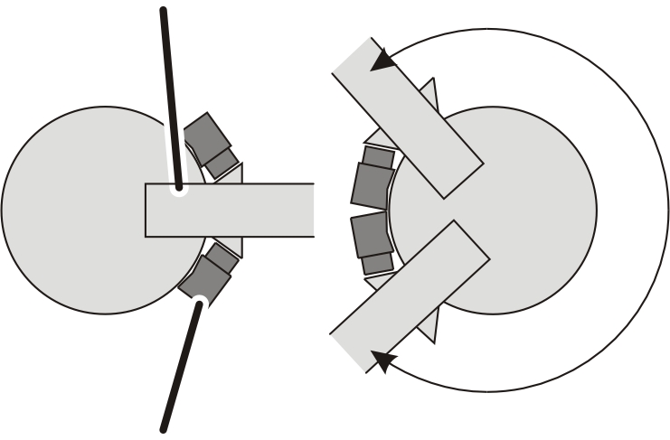
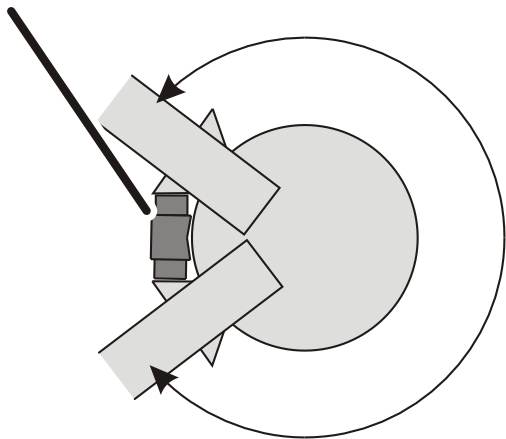
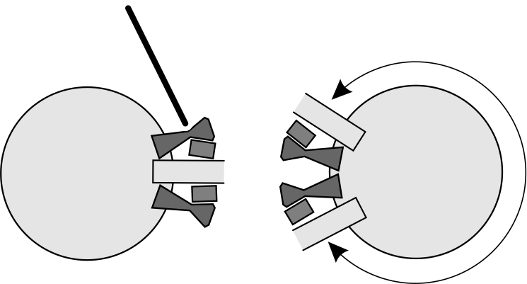
Defining the slewing range
|
Slewing stops |
|
|
| |
─
|
Size |
Slewing range from |
Slewing range to |
|
VS273 and VS323 |
0° |
240° |
|
VS355 to VS558 |
0° |
255° |
Slewing range when there are two slewing stops at 15° increments.
─
|
Slewing stop |
|
|
| |
|
Jib arm |
|
|
Size |
Slewing range |
Dead zone |
|
VS273 and VS323 |
285° |
75° |
|
VS355 to VS558 |
300° |
60° |
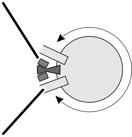
Slewing range when there is a slewing stop at 15° increments.
Limitations:
─ VS273 and VS323: the slewing range cannot be limited between 240° and 285°, nor beyond 285°.
─ VS355 to VS558: the slewing range cannot be limited between 255° and 300°, nor beyond 300°.
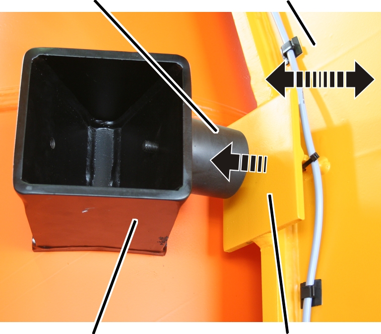
Installing the slewing stops
|
Head plate |
Safety buffer |
|
| |
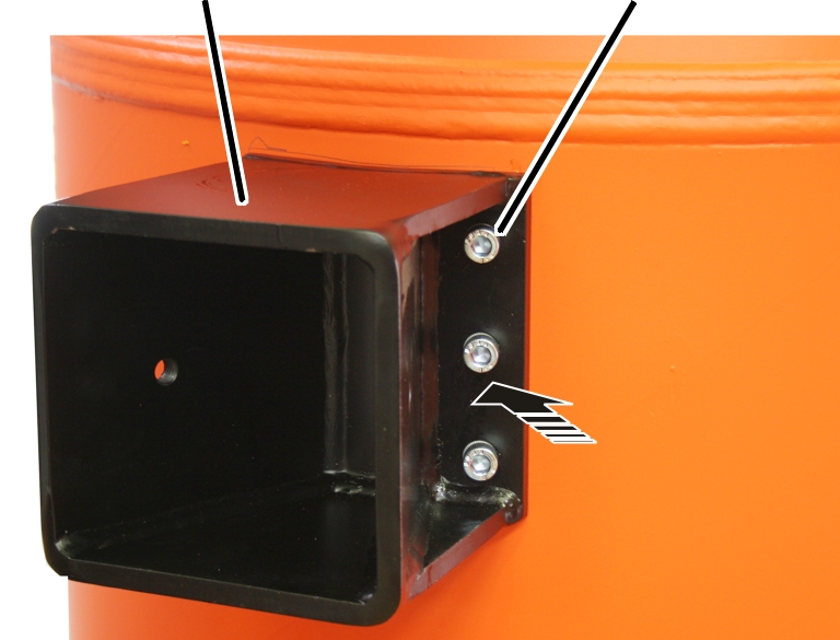
|
Rib screw |
Buffer mount |
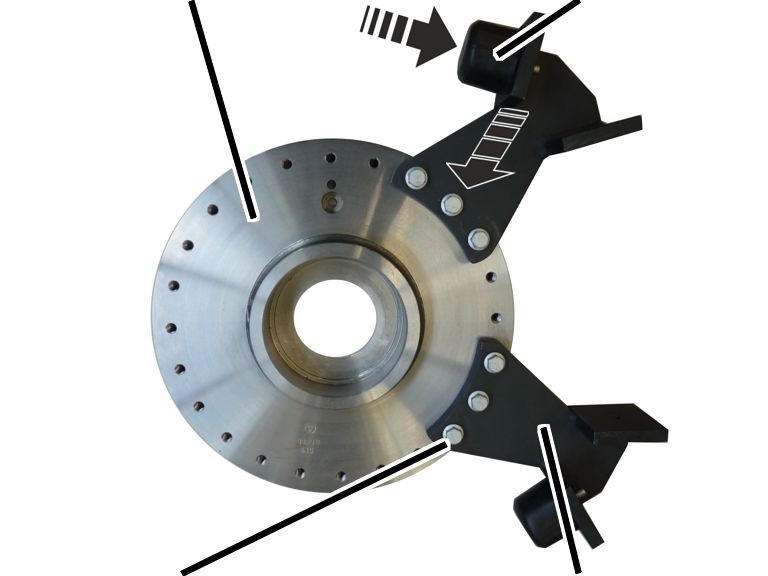
 Screw the safety buffer
into the buffer mount.
Screw the safety buffer
into the buffer mount.
Slew the jib arm until it
is just a few degrees before the end of the desired slewing range (e.g. before
reaching an obstacle or the building wall).
Hold the slewing stop at
the most suitable screw holes.
Screw the slewing stop in
place using rib screws (3x each). 115 Nm.
|
Size |
Rib screws (3x) |
|
VS273 |
M12x25 |
|
VS232 to VS457 |
M12x30 |
|
VS558 |
M12x45 |