Danger due the the trolley rolling away!
The trolley may roll away during jib arm installation, and injure persons, when it is not sufficiently secured.
Secure the trolley on the jib arm against rolling away.
All individual components have now been affixed to the jib arm. The jib arm is now installed on the pillar and connected to it.
|
|
Danger due the the trolley rolling away! The trolley may roll away during jib arm installation, and injure persons, when it is not sufficiently secured. Secure the trolley on the jib arm against rolling away. |
|
|
Pins |
|
| |
|
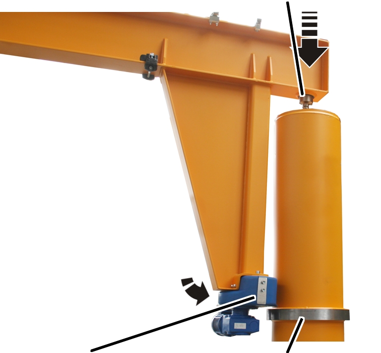
Slewing gear unit |
Thrust ring |
 Fasten the pre-installed
jib arm to a suitable lifting device (e.g forklift truck, crane, etc.).
Fasten the pre-installed
jib arm to a suitable lifting device (e.g forklift truck, crane, etc.).
It must be secured against tipping and slippage.
Fasten the individual
components (e.g. trolley, mobile control) to the jib arm. They must not roll
away unchecked.
Observe occupational
health and safety requirements and raise the jib arm.
Insert the jib arm into
the slew bearing from above using the pins.
Support the slewing gear
unit on the thrust ring using the supporting rolls.
The pillar is only vaguely indicated in the following figures to allow the worksteps to be better identified.
The worksteps in the pillar are carried out through the access portal in the upper part of the pillar.
In the pillar:
|
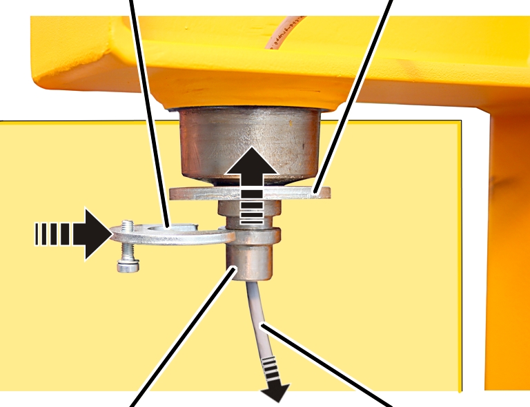
Mounting device |
Ring plate |
|
| |
|
Pins |
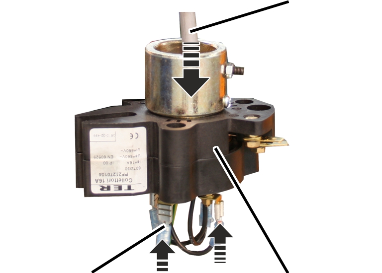
Connection cable |
Push the connection cable
through the hole in the jib arm from above, and into the pillar.
Loosely screw the
fillister-head screw M8x25 into the fastening component.
Push the ring plate onto
the pin from below.
Push the side of the
fastening component onto the pin.
|
| |
|
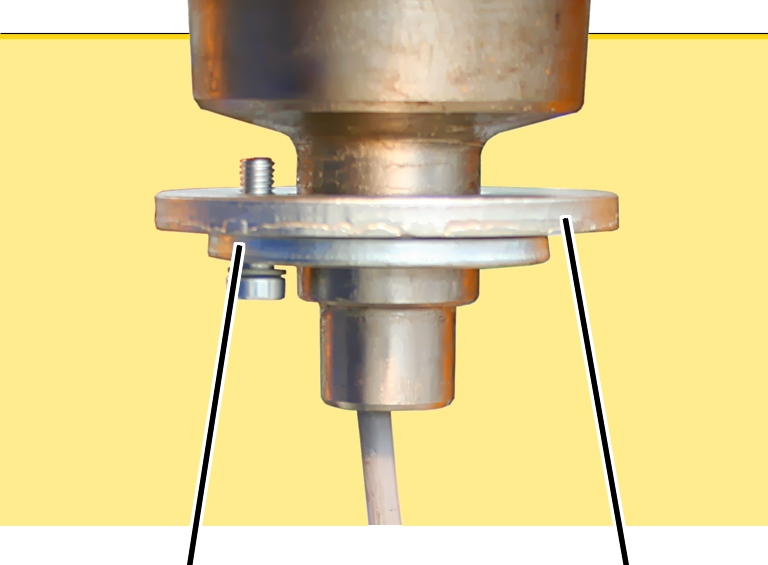
Mounting device |
Ring plate |
 Screw the ring plate and
the fastening component together. Screw until hand-tight.
Screw the ring plate and
the fastening component together. Screw until hand-tight.
This workstep only applies for a power supply with more than four wires. Otherwise leave out this section out, and continue with the next section.
|
|
Connect the eight-pin slip
ring.
See the instructions “Installing the 8-pin slip ring” (AN 120217)
Outside the pillar:
|
|
Connection cable |
|
| |
|
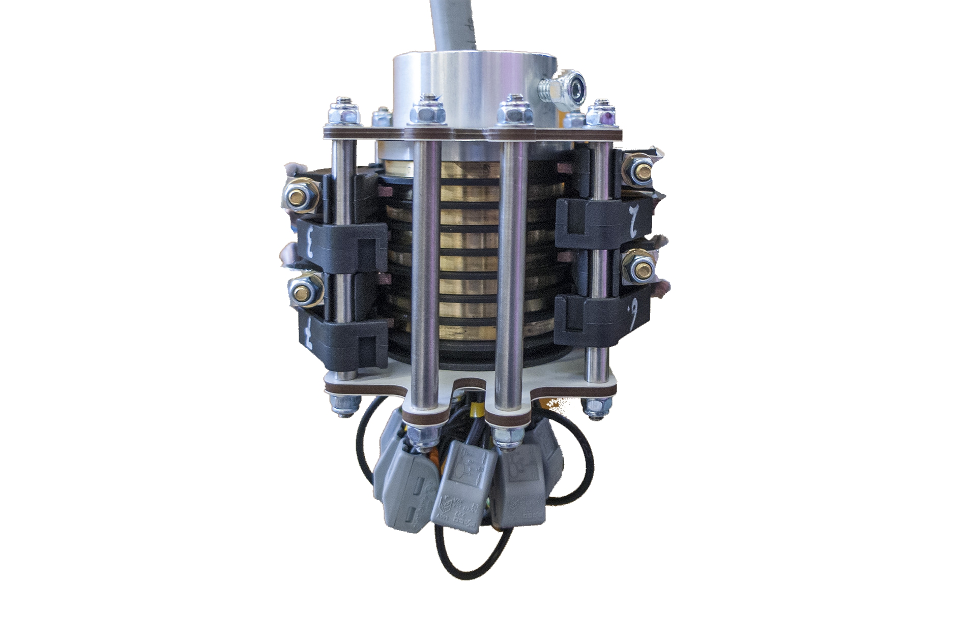
Cable lug |
Slip ring |
Strip the connection cable
(originating from the jib arm) and attach the cable lug.
Guide the connection cable
downwards through the slip ring from above, and connect it at the bottom. See
the wiring diagram.
In the pillar:
|
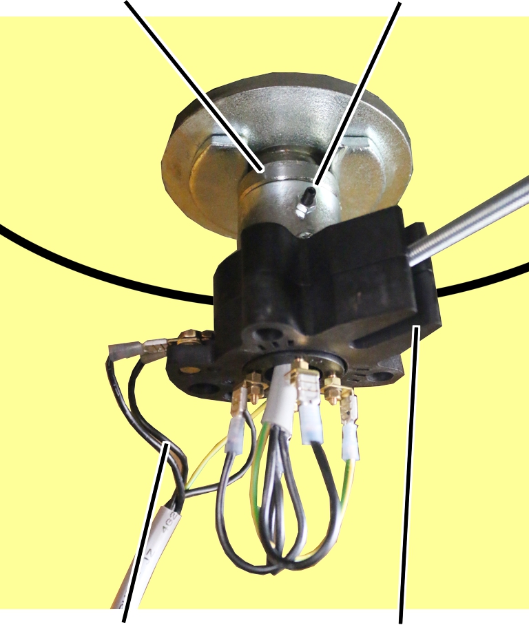
Pins |
Stud |
|
| |
|
Connection cable from the mains switch |
Slot |
Push the slip ring onto
the pin on the jib arm.
Rotate the slip ring so
that the screw for the mount catches in the slot on the side of the slip
ring.
Screw the slip ring onto
the pin using studs.
Strip the cable from the
mains switch and attach the cable lug.
Connect the cable from the
mains switch to the slip ring.
See the wiring diagram.
|
| |
|
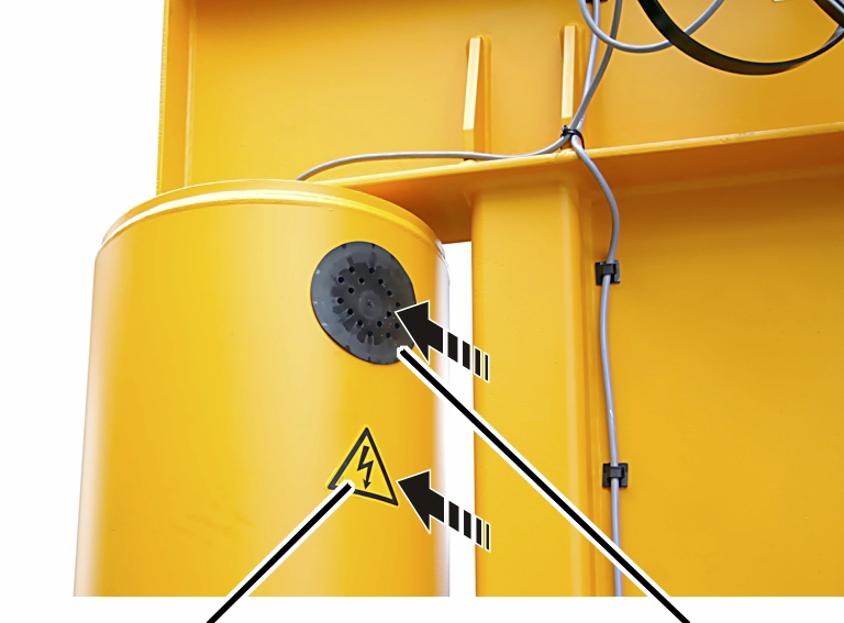
Adhesive sign |
Cover |
Insert the cover into the
access portal on the pillar.
Stick the adhesive sign
onto the pillar below the cover.