Only with a slewing gear unit in the working and traffic area
This section only applies when the slewing gear unit is suspended so low that it is located in the working and traffic area.
The figures show installation of the guard plates on the safety plate. Installation of the guard plates on the adjustable brake is, essentially, no different.
Installing the guard plates
 The crane lower edge
dimension can be found in the documentation.
The crane lower edge
dimension can be found in the documentation.
The guard plates are required up to the lower edge dimension specified in the table:
|
Size |
Slewing by hand |
Slewing drive |
|
273 |
3500 |
3700 |
|
323 |
3700 |
3900 |
|
355 |
3700 |
3900 |
|
406 |
3800 |
4100 |
|
457 |
3800 |
4100 |
|
558 |
4200 |
4400 |
|
660 |
4200 |
4400 |
|
762 |
4700 |
5000 |
|
Guard plate |
|
|
| |
|
|
Clip nuts |
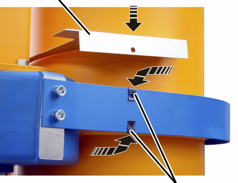
Place clip nuts M6 (4x)
onto the safety plate.
Put the upper guard plate
on.
|
Rib screw |
Guard plate |
|
| |
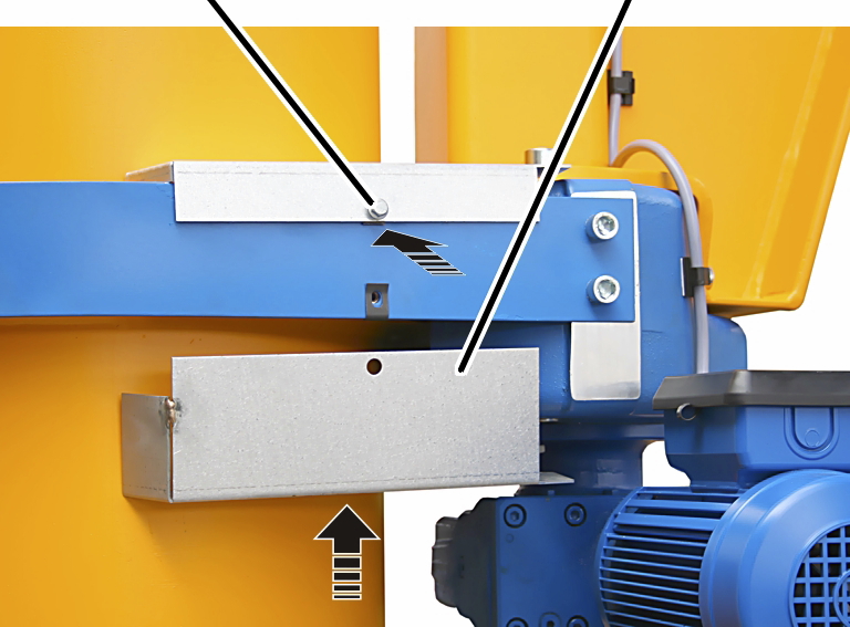
Put the lower guard plate
on.
Screw the guard plate in
place using rib screws M6x16 (4x). 19 Nm.