Only with a jib crane with adjustable brake
The figures show the installation of the adjustable brake on the jib crane up to size 457. Installation on larger jib cranes is, essentially, no different.
Installing the fork
|
Fork |
Fillister-head screw |
|
| |
|
|
Roller box |
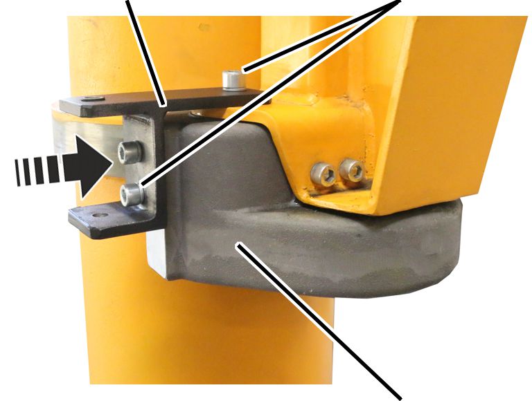
 Screw the fork onto the
side of the roller box.
Screw the fork onto the
side of the roller box.
|
Size |
Number |
Fillister-head screw |
Tightening torque |
|
273 |
4x |
M10x20 |
20 Nm |
|
323 - 457 |
4x |
M12x20 |
35 Nm |
|
558 - 660 |
8x |
M12x25 |
35 Nm |
|
762 |
8x |
M16x25 |
80 Nm |
Installing the brake band
|
Fillister-head screw with spring lock washer |
|
|
| |
|
|
Brake band |
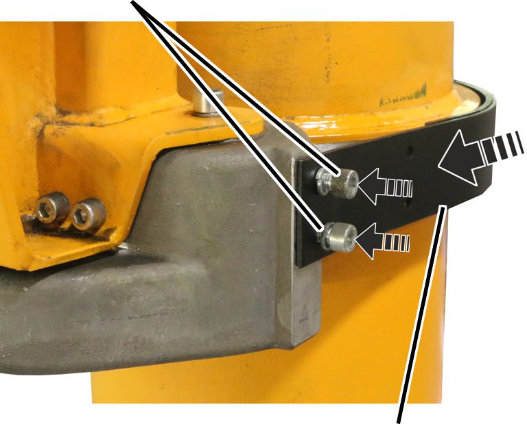
Place the brake band
around the thrust ring.
Screw the brake band onto
the roller box on the side opposite the guidance device.
|
Size |
Number |
Fillister-head screw |
Tightening torque |
|
273 |
4x |
M10x20 |
20 Nm |
|
323 - 457 |
4x |
M12x20 |
35 Nm |
|
558 - 660 |
8x |
M12x25 |
35 Nm |
|
762 |
8x |
M16x25 |
80 Nm |
|
Fork |
Guidance device |
|
| |
|
Fillister-head screws |
|
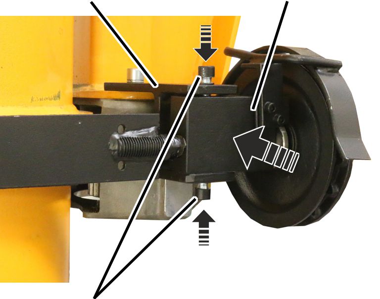
Push the brake band into
the fork on the same side as the guidance device.
Screw it in place by hand
from above and below using fillister-head screws and spring lock washers.
|
Size |
Number |
Fillister-head screw |
Tightening torque |
|
273 |
2x |
M10x20 |
45 Nm |
|
323 - 558 |
2x |
M12x25 |
70 Nm |
Installing the chain
|
Reel wheel |
|
|
| |
|
Chain |
|
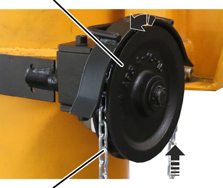
Pull the chain through the
reel wheel.
Connect both ends of the
chain to each other using a C-shaped chain link.