Only for jib cranes with
mains switch in the pillar
This section only applies if the jib crane has a hole for a
mains switch in the pillar.
Note
On jib cranes with a mains switch, a mains switch is
installed in the pillar. The power supply to the entire crane can be
disconnected using the mains switch later on.
Installing the
mains switch
|
Fillister-head screw M5x20 |
Protective conductor |
|
|
|
Power
line from the pillar base and cable to the slip ring |
Seal |
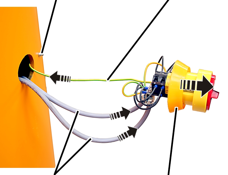
 Fit the seal on the main
switch.
Fit the seal on the main
switch.
Bolt the protective
conductor to the pillar from the inside, using a fillister-head screw M5x20 and
a hexagonal nut.
Connect the power line to
the mains switch. See the wiring diagram.
Connect the cable from the
pillar cap to the mains switch. See the wiring diagram.
Screw the cables on the
mains switch using cable clamps.
Fit the mains switch into
the pillar, and clamp it in place from the outside using screws.
Only for jib cranes with
mains switch on the wall
This section only applies if the jib crane has no hole
for a mains switch in the pillar (e.g. if the pillar is short) and the mains
switch is attached to the wall.
Note
No mains switch is installed in the pillar on jib
cranes with a short pillar. The switch must be attached as a wall switch in its
own electrical installation near the jib crane. This version also requires a
protective conductor connection, which is connected on the pillar next to the
access portal.
Fitting the
protective conductor connection
|
|
Access portal |
|
|
|
Hole Ø 5.5 mm |
|
 Connect the jib crane to
the power line as instructed in the wiring diagram.
Connect the jib crane to
the power line as instructed in the wiring diagram.
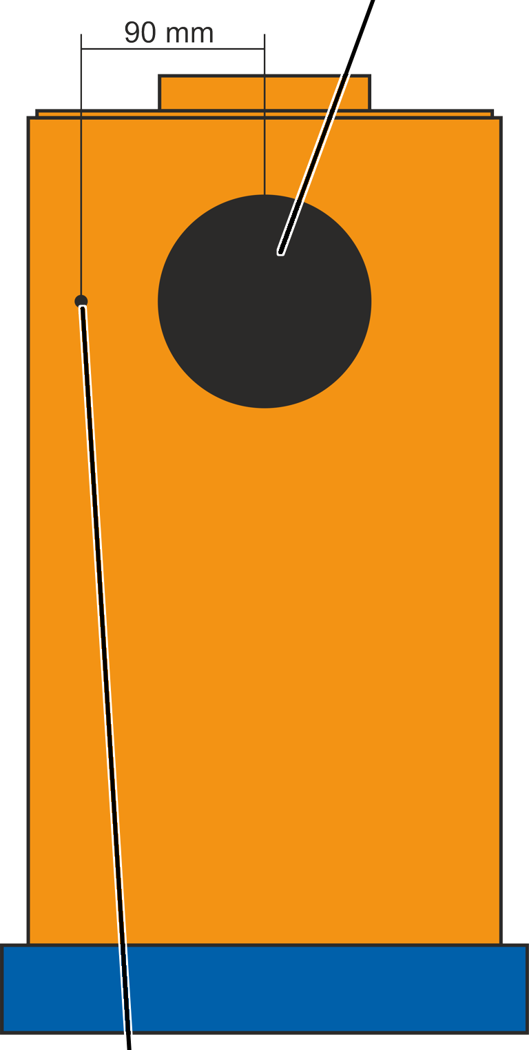
Insert Ø 5.5 mm
hole in the pillar about 90 mm from the centre of the access portal.
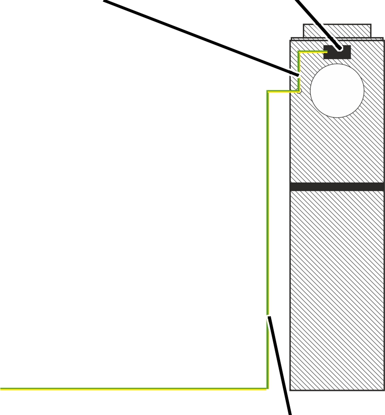
Crimp ring cable lug M5 on
the protective conductor of the line.
|
Protective conductor |
Slip
ring |
|
|
|
|
Protective conductor connection |
 Screw the protective
conductor with ring cable lug and protective conductor connection tight on the
pillar using screw M5x30.
Screw the protective
conductor with ring cable lug and protective conductor connection tight on the
pillar using screw M5x30.
Secure the other end of
the protective conductor connection to the slip ring with a flat plug.
Affix the "Protective
cover" label next to the hole.