Depending on the crane design, an electrical slew switch-off
is now installed which limits the slewing range of the crane electrically.
The electrical slew switch-off is comprised of one or two
limit switches that are fastened to the jib bracket, and flexible plastic
switching lugs that are positioned on the pillar using a special tape fastener.
Assigning limit
switches
Depending on the control and switch-off (braking function
and/or shut-down), a different number of limit switches must be installed at
various positions.
Only with a control in the
panel or ABULiner frequency converter
For braking function:
Mounting plate (with two limit switches), mounted on left or
right on the jib bracket.
|
Switch-off |
Slewing direction |
Position of limit switch |
|
Braking function |
left |
top |
|
Braking function |
right |
bottom |
For braking function or shut-down:
First mounting plate (with two limit switches), mounted on
one side of the jib bracket.
|
Switch-off |
Slewing direction |
Position of limit switch |
|
Shut-down |
left |
top |
|
Braking function |
left |
bottom |
Second mounting plate (with two limit switches), mounted on
the other side of the jib bracket.
|
Switch-off |
Slewing direction |
Position of limit switch |
|
Shut-down |
right |
top |
|
Braking function |
right |
bottom |
Only with electronic control
in the electrical system housing
For braking function:
Mounting plate (with a limit switch), mounted on left or
right on the jib bracket.
|
Switch-off |
Slewing direction |
Position of limit switch |
|
Braking function |
left and right |
top |
For braking function or shut-down:
First mounting plate (with a limit switch), mounted on one
side of the jib bracket.
|
Switch-off |
Slewing direction |
Position of limit switch |
|
Braking function |
left and right |
bottom |
|
Shut-down |
left |
top |
Second mounting plate (with a limit switch), mounted on the
other side of the jib bracket.
|
Switch-off |
Slewing direction |
Position of limit switch |
|
Shut-down |
right |
top |
Only with a slew switch-off
on a jib crane with cylindrical pillar cap (size 273 to 558)
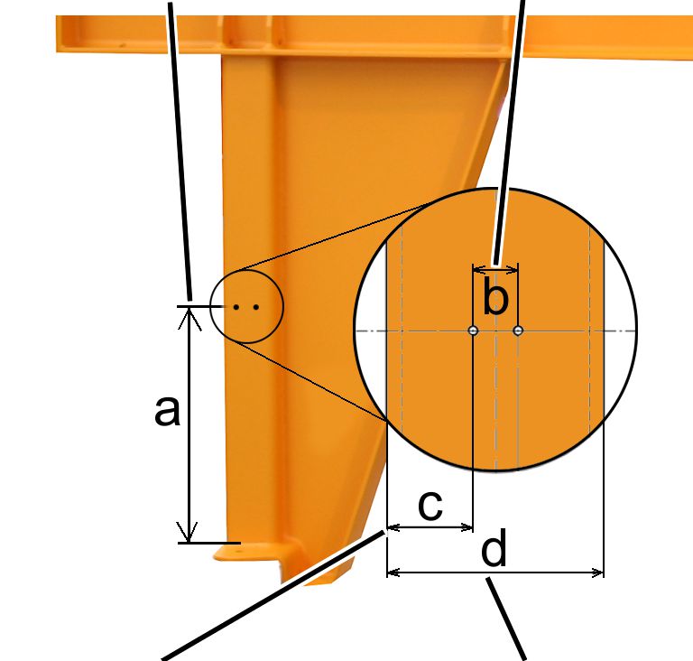
Drilling the
holes in the jib bracket
|
a =
distance between drilled holes and lower edge |
b =
distance between
drilled holes |
|
|
|
c =
distance between first drilled hole and edge |
d =
width of jib bracket
square bar |
 Drill threaded holes M6
(2x) in the jib bracket square bar.
Drill threaded holes M6
(2x) in the jib bracket square bar.
Distance between drilled holes and lower edge of the jib bracket
(a): 350 mm
|
Size |
Dimension b [mm] |
Dimension c [mm] |
Dimension d [mm] |
|
VS273 |
25 |
27.5 |
80 |
|
VS323 |
25 |
37.5 |
100 |
|
VS355 |
25 |
37.5 |
100 |
|
VS406 |
35 |
42.5 |
120 |
|
VS457 |
35 |
42.5 |
120 |
|
VS558 |
35 |
25 |
160 |
Installing the
limit switch
|
Pillar |
Jib
bracket |
|
|
|
Threaded
plate |
Rib
screws M6x20 |
 Screw the mounting plate
loosely in place using rib screws M6x20.
Screw the mounting plate
loosely in place using rib screws M6x20.
Only with a slew switch-off
on a jib crane with conical pillar cap (size 660 and 762)
Installing the
limit switch
|
Vertical
beam
on the jib bracket |
|
|
|
|
Pillar |
Threaded
plate |
Screw the mounting plate
on the side of the beam on the jib bracket using the clamping piece.
25 Nm.
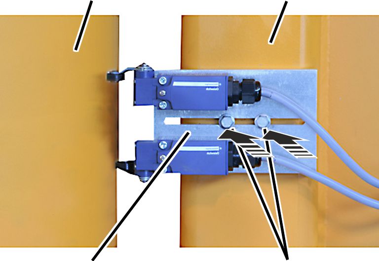
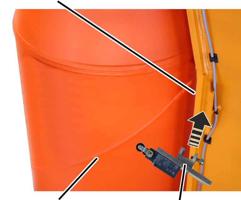
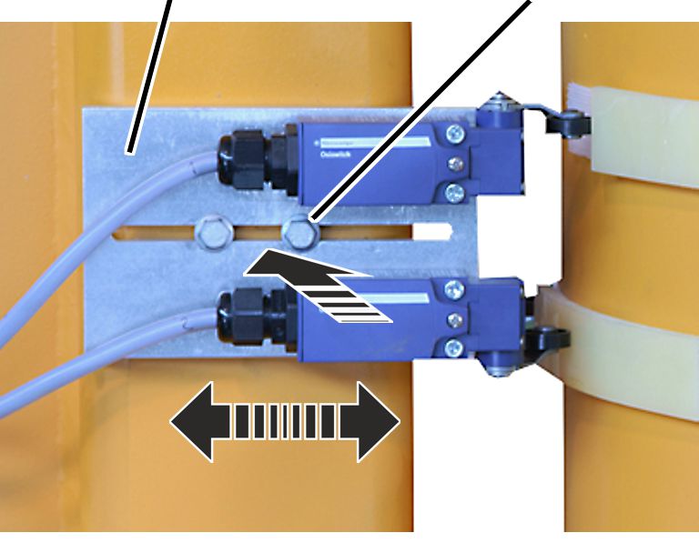
Attaching the
tape fastener and switching lugs
The figures show the attachment of the tape fastener and
switching lugs on a jib crane with a cylindrical pillar cap. The attachment to a
jib crane with conical pillar cap is, essentially, no different.
On every switching point:
|
Actuating cam |
Limit
switch for shut-down |
|
|
|
Tape
fastener |
Limit
switch for braking function |
Clean the pillar around
the limit switch thoroughly.
Slew the jib arm so that
it is in the required switching point for the braking function or shut-down.
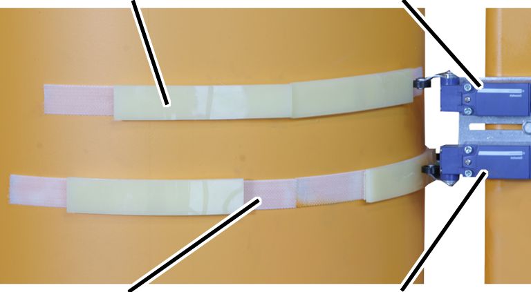
Adhere the tape fastener
(2x) to the pillar centred under the limits switches.
The two tape fasteners should be at a distance of about
77 mm to each other.
The tape fastener for the shut-down (top) should be adhered with
an offset of a few centimetres in the slewing direction.
Press the switching lugs
onto the tape fastener so that the limit switch is activated at the respective
switching point.
Repeat the procedure for
all switching points.
Setting the
limit switch and screwing it in place
|
Threaded
plate |
Rib
screw M6x20 |
|
|
Move the bolted flange so
that the limit switch is reliably activated by the switching lugs.
Screw the rib screws M6x20
in place. 13 Nm.
Connecting the
limit switch
Lay the connection cable
from the limit switch to the control.
Attach the connection
cable to the jib bracket using adhesive clips.
Guide the connection cable
into the control and connect it. See the wiring diagram.