Only with an open main
girder connection
If the main girder connection is not closed, the wire rope
hoist can be pushed onto the lower flange.
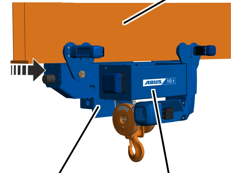
In the following, the assembly on a main girder is shown as a
box girder. The installation on an I-beam does not differ significantly.
|
|
Main
girder |
|
|
|
Counterweight side |
Wire
rope hoist |
 Rotate the wire rope hoist so
that the counterweight side faces the power supply.
Rotate the wire rope hoist so
that the counterweight side faces the power supply.
Observe the occupational health and safety
requirements and raise the wire rope hoist.
Push the wire rope hoist from
the open side onto the main girder connection and set it down with the
wheels.
Only with a closed main
girder connection
In the following, the assembly on a main girder is shown as a
box girder. The installation on an I-beam does not differ significantly.
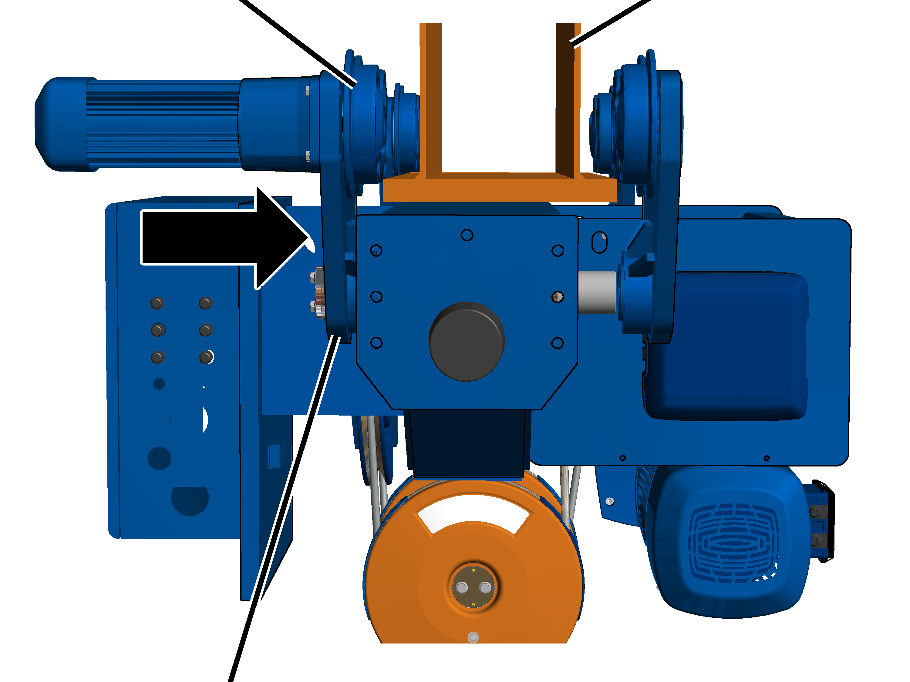
Disassembling
drives
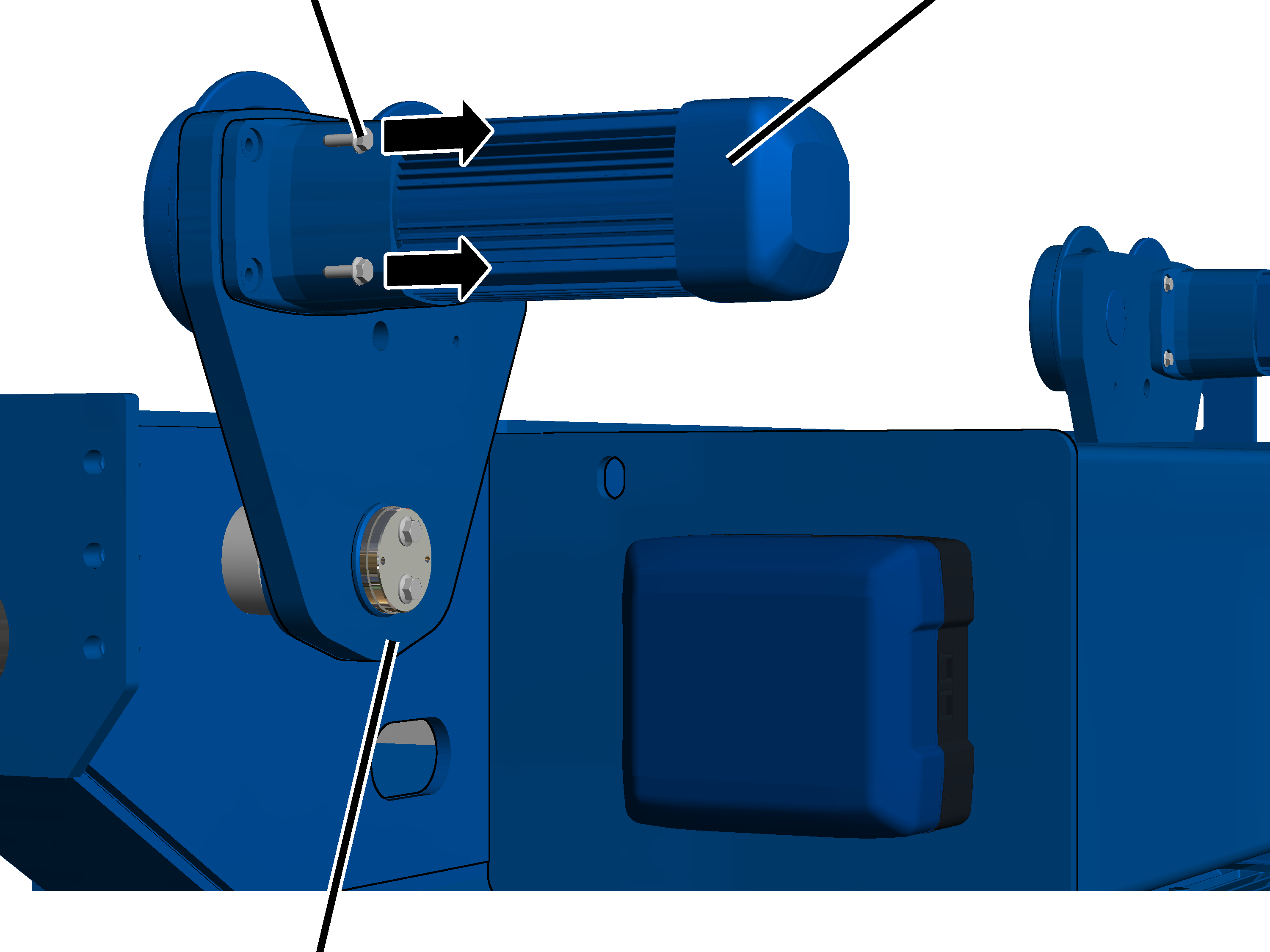
To facilitate the installation, two of the four drives on the
side panels on the drum side of the wire rope hoist are disassembled.
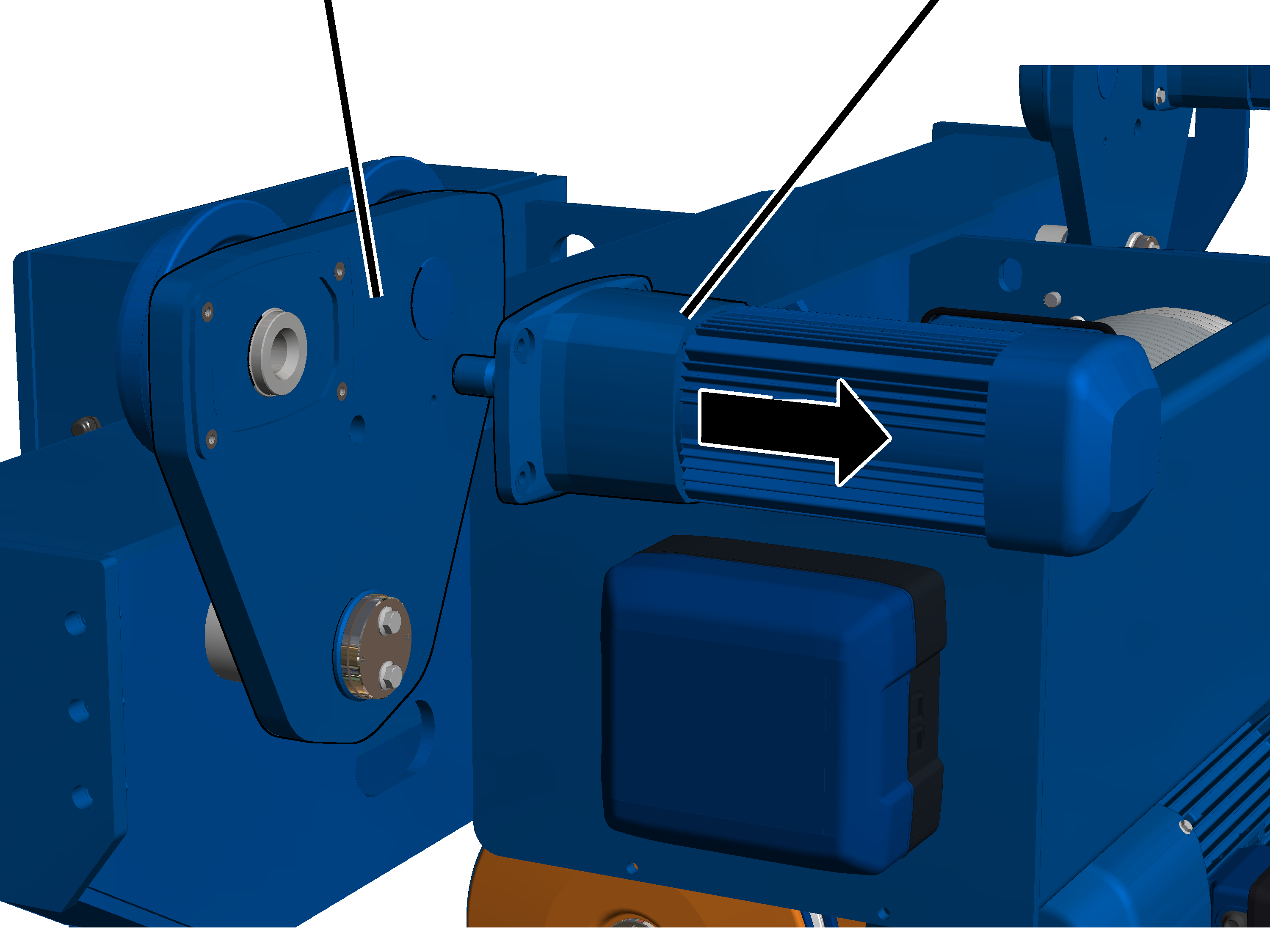
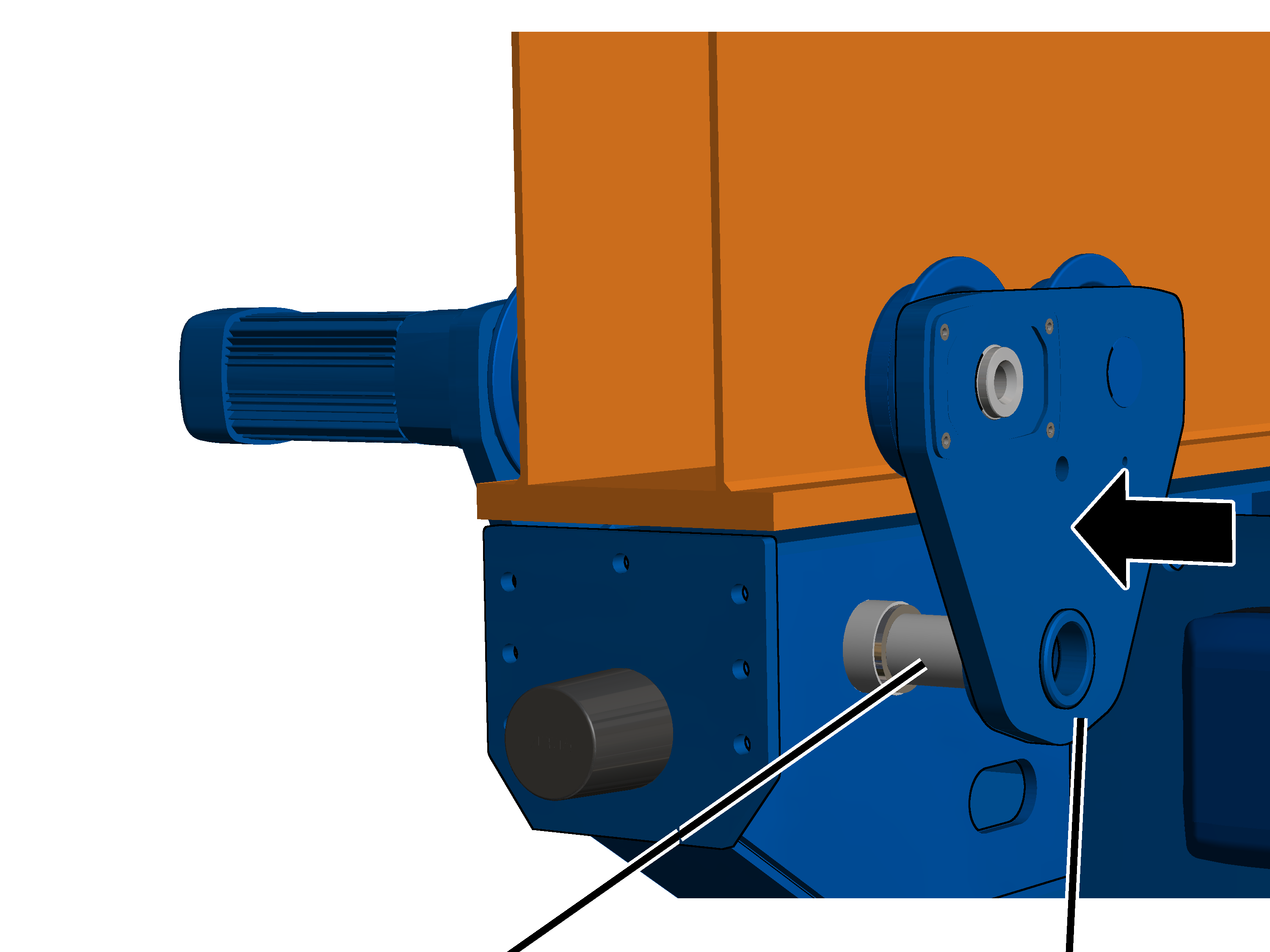
On both drives on the drum side:
|
Rib
screw |
Drive |
|
|
|
Side
panel |
|
Release the rib screws (4x) on
the drive.
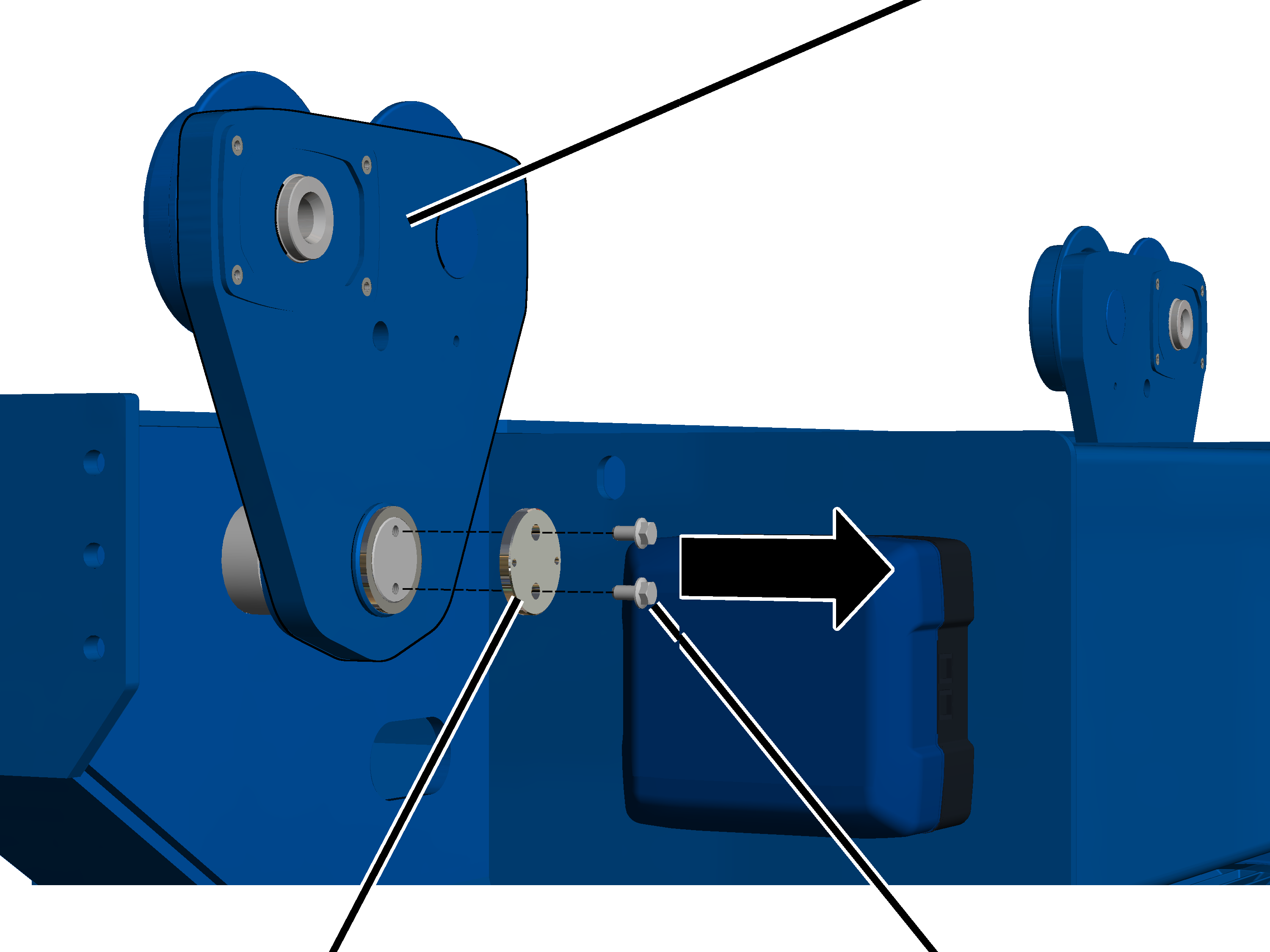
|
Side
panel |
Drive |
|
|
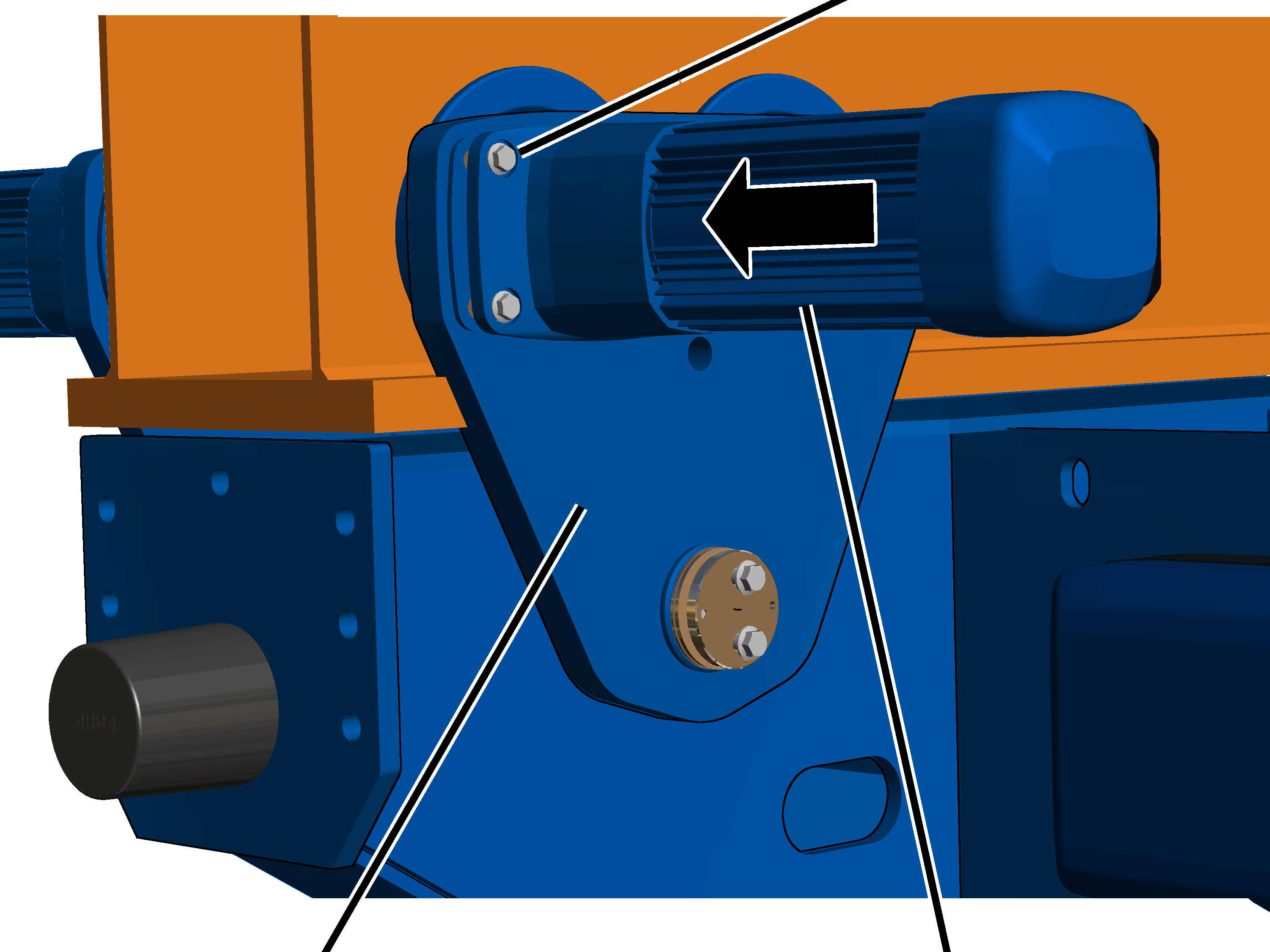
Pull the drive out of the side
panel.
Detaching the
side panels
In order to be able to install the wire rope hoist on the
main girder, the side panels are pushed outward on the bearing bolt.
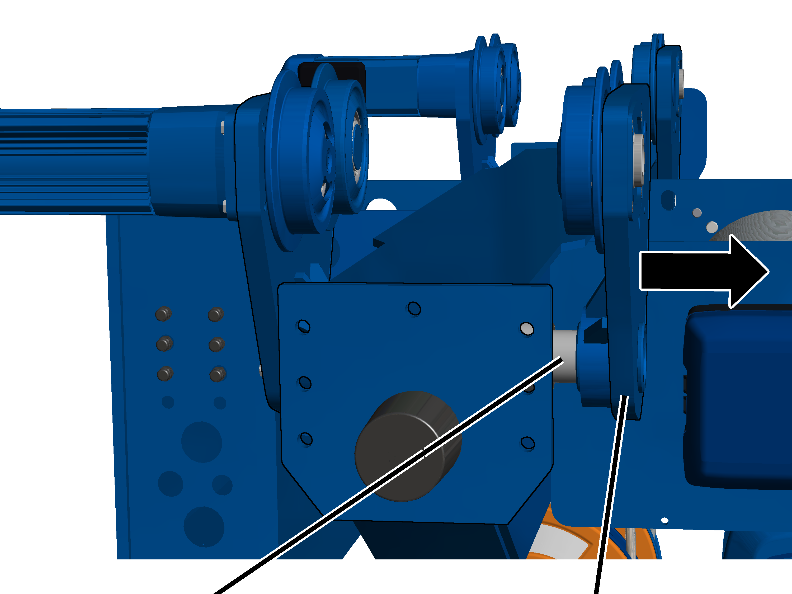
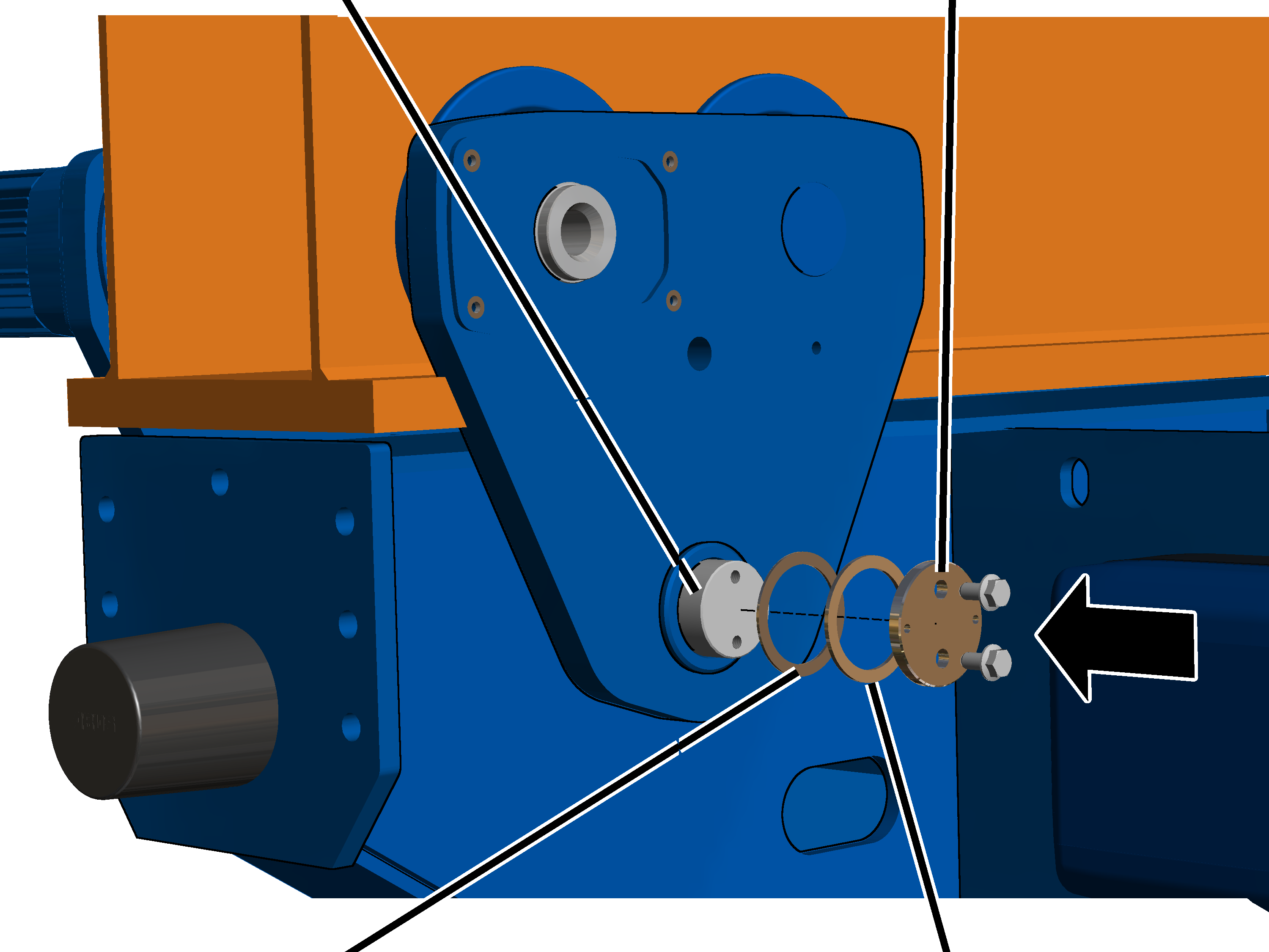
On both drives on the drum side:
|
|
Side
panel |
|
|
|
Cover |
Rib
screw |
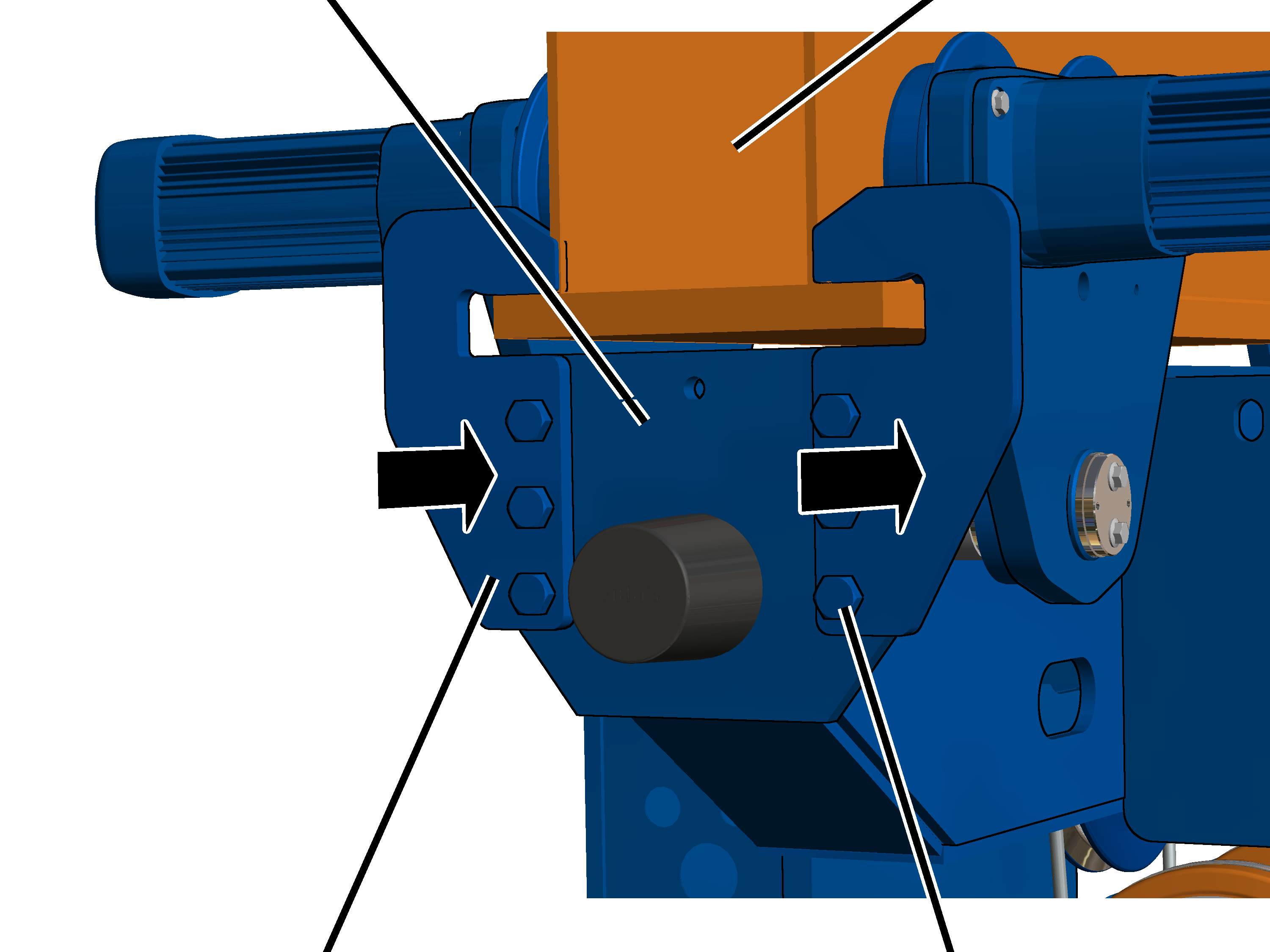
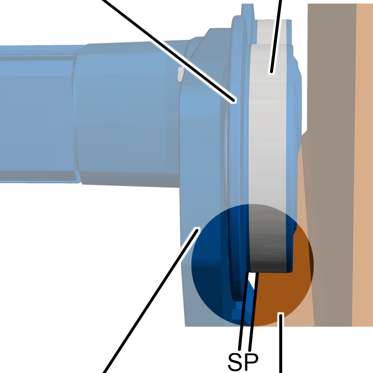
Release the rib screws M10x20
(2x) on the cover.
Pull the cover from the bearing
bolt.
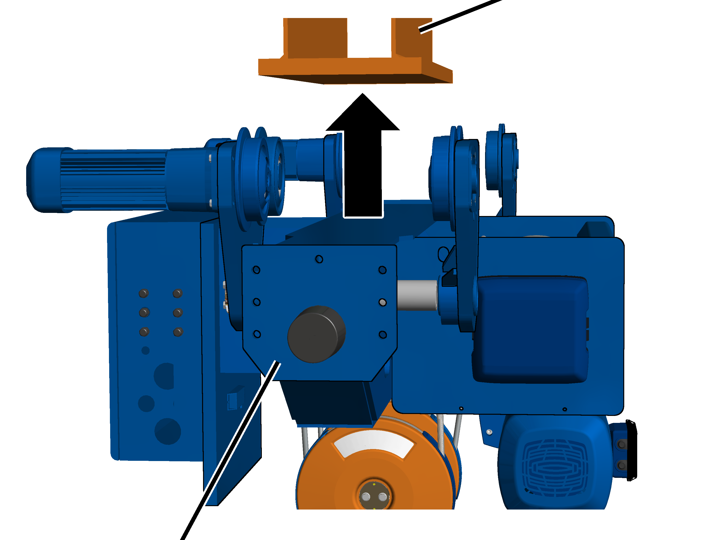
|
|
|
Bearing
bolt |
Side
panel |
Push the side panel outward on
the bearing bolt.
The wire rope hoist must be pushed
apart so far that the distance between the wheels is wider than the lower
flange.
Installing the
wire rope hoist on the main girder
|
|
Main
girder |
|
|
|
Wire
rope hoist |
|
Lift
the wire rope hoist under the main girder using, for example, a lift
truck.
On both drives on the counterweight side:
|
Wheel |
Main
girder |
|
|
|
Side
panel with drive |
|
Rotate the wire rope hoist so
that the counterweight side faces the power supply.
Push the wheels on the side
panel with the drive onto the main girder.
The wheels must lie with their
running surface fully on the lower flange!
On both drives on the drum side:
|
|
|
Bearing
bolt |
Side
panel |
Push the side panel onto the
bearing bolt.
The wheels must lie with their running surface fully on the
lower flange!
|
Bearing
bolt |
Cover |
|
|
|
Shim
washer |
Support
washer |
Push the shim washer and support
washer onto the bearing bolt.
Screw the cover onto the bearing
bolt with the rib screws M10x20. 75 Nm.
Installing the
drive
Now the drives are installed on the side panels.
On both drives on the drum side:
|
|
Rib
screw |
|
|
|
Side
panel |
Drive |
Slide the drive in the driven
wheel on the side panel.
Bolt on the drive with the rib
screws M10x30 (4x). 75 Nm.
The chamfer of the washer must point toward the bolt head.
The lift-off prevention device must grip around the lower flange
or the flange of the main girder.
The measured value may not be larger than 2 mm on either
side.