Comply with occupational health
and safety requirements.
Comply with occupational health
and safety requirements.
If the wheel is damaged or worn, it must be replaced by a new wheel.
Comply with occupational health
and safety requirements.
Relieve the load of the end
carriage on the wire rope hoist near the wheel from below.
|
|
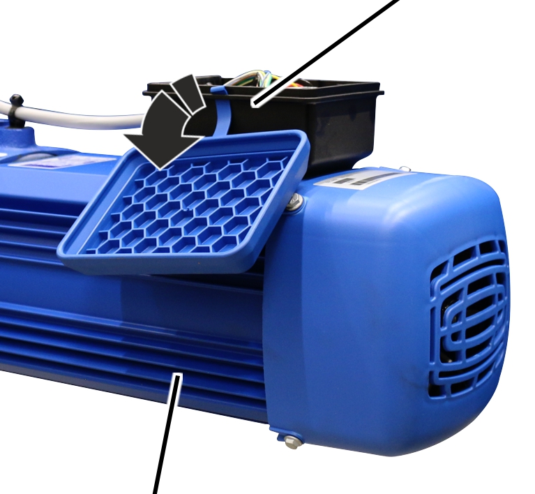
Connector housing |
|
| |
|
Drive |
|
 Open the
connector housing on the drive.
Open the
connector housing on the drive.
Disconnect the connection cable
from the coupler plug.
Determine the weight of the
drive. See the ABUS Drive product manual.
Secure the drive so that the
weight can be held safely and the output shaft will not be subject to load (e.g.
insert in round sling).
|
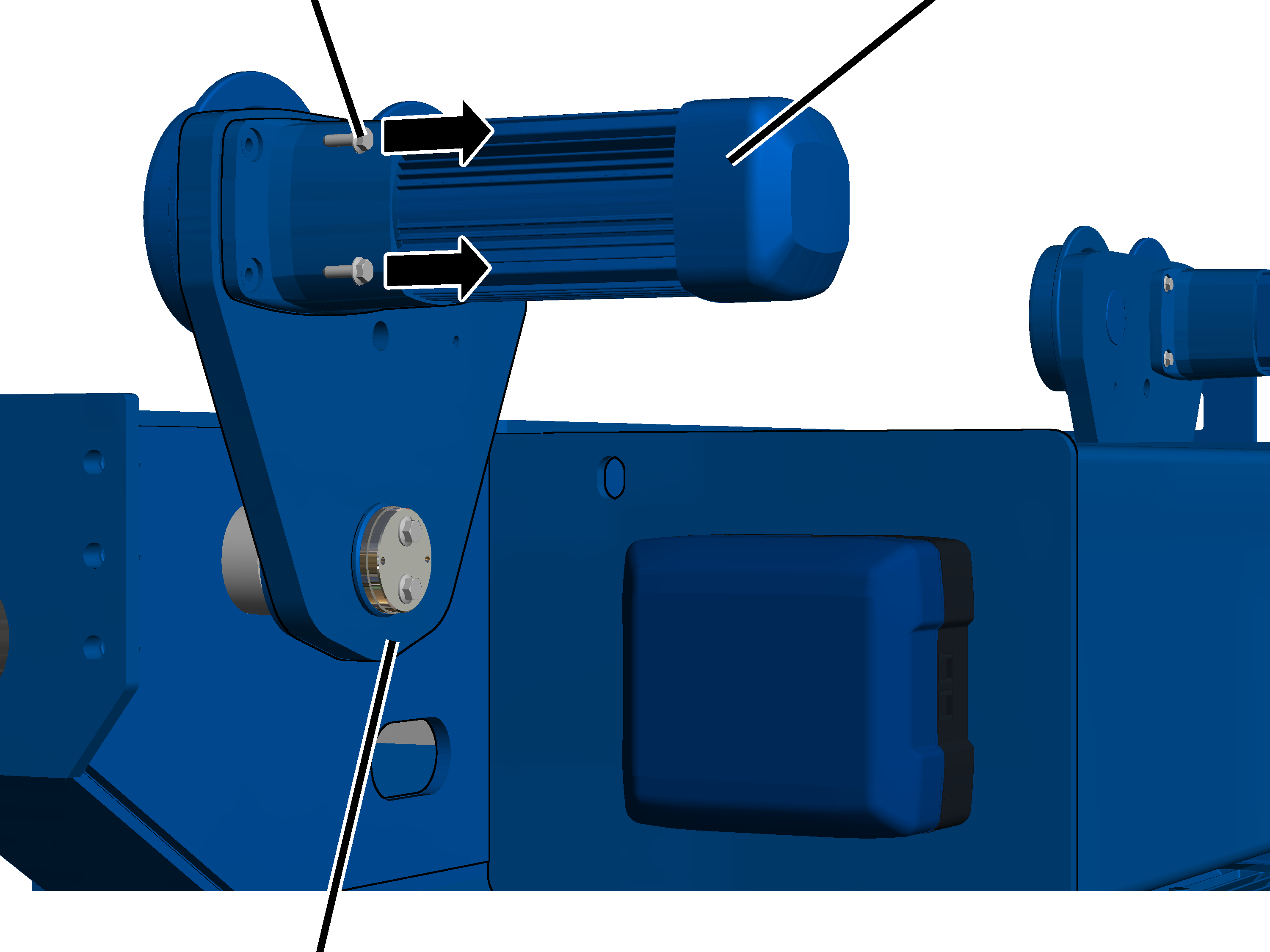
Rib screw |
Drive |
|
| |
|
Side panel |
|
Unscrew the rib screws (4x) from
the drive on the side panel.
|
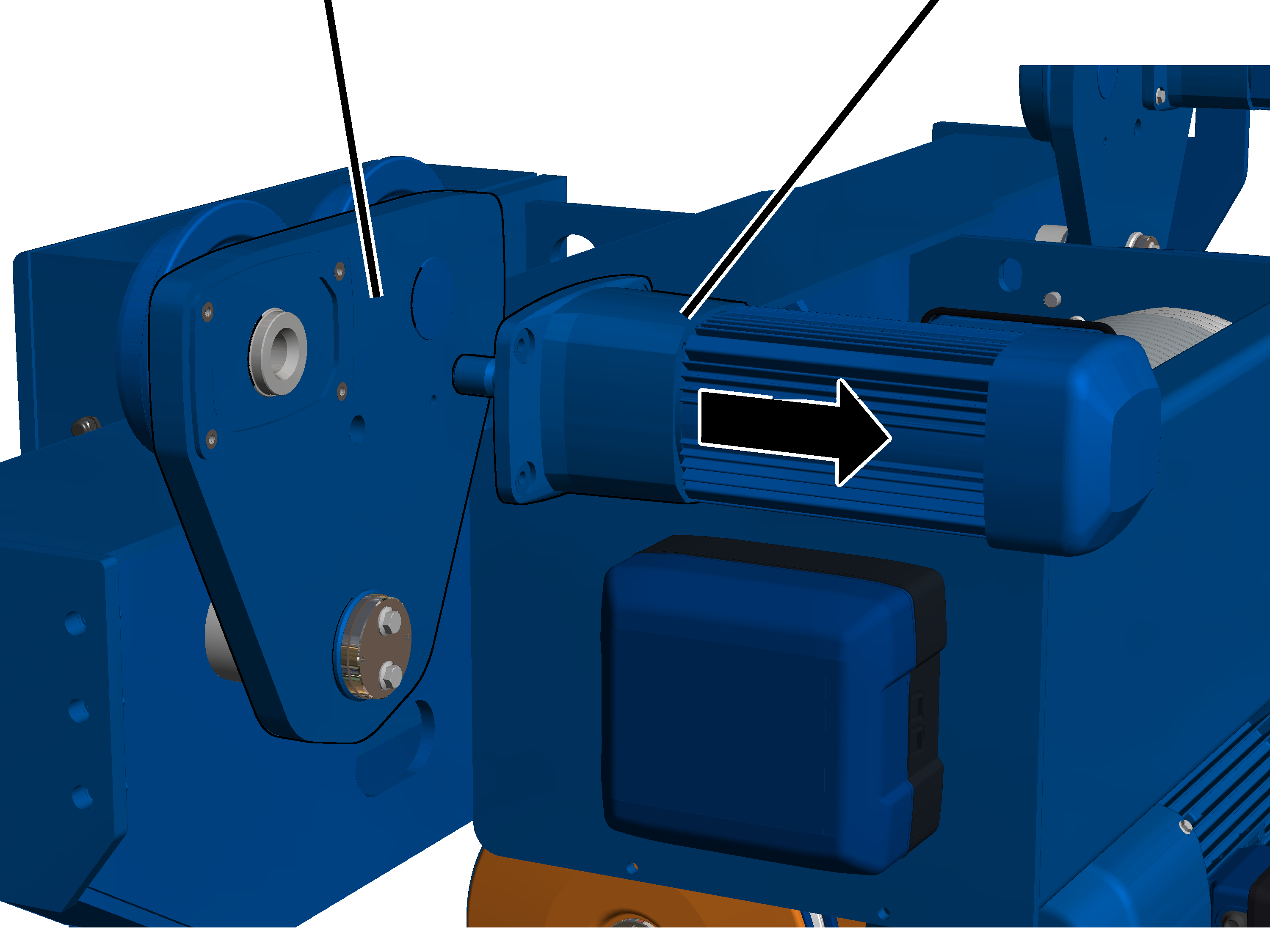
Side panel |
Drive |
|
| |
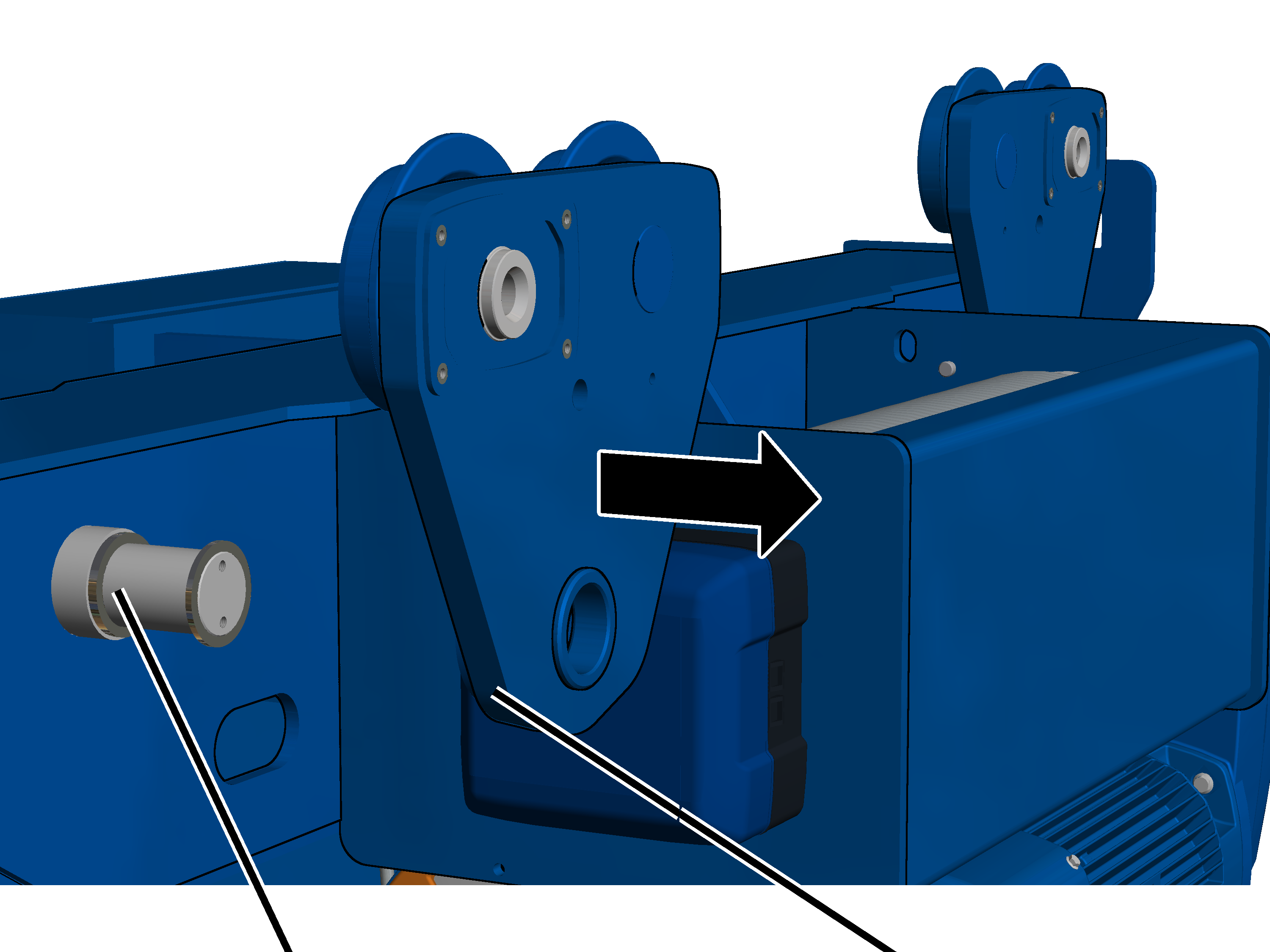
Pull the drive out of the side
panel.
|
|
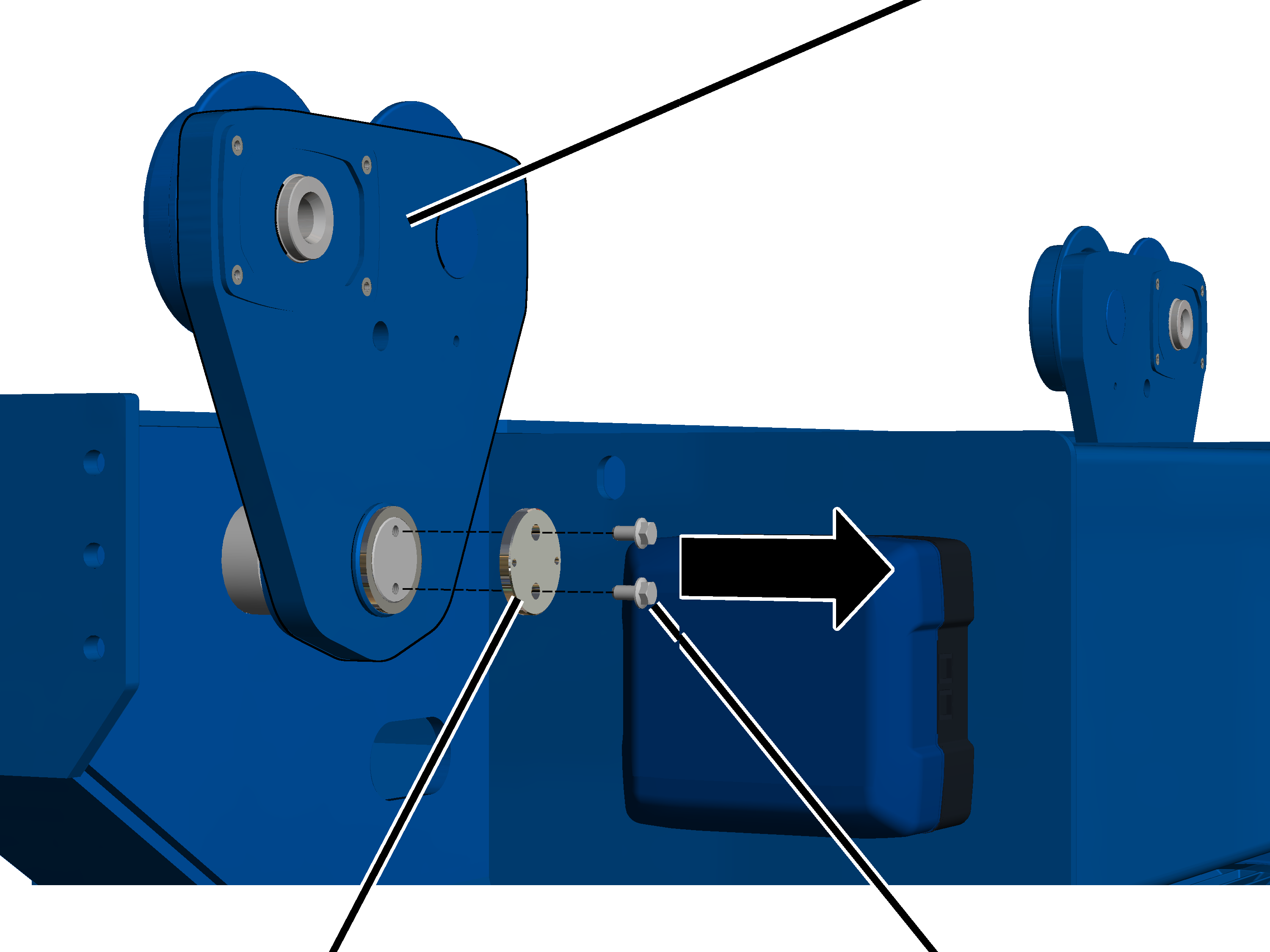
Side panel |
|
| |
|
Cover |
Rib screw |
Release the rib screws M10x30
(2x) on the cover of the side panel.
Pull the cover and rib screws
from the side panel.
|
| |
|
Bearing bolt |
Side panel |
Pull the side panel from the
bearing bolt in the end carriage.
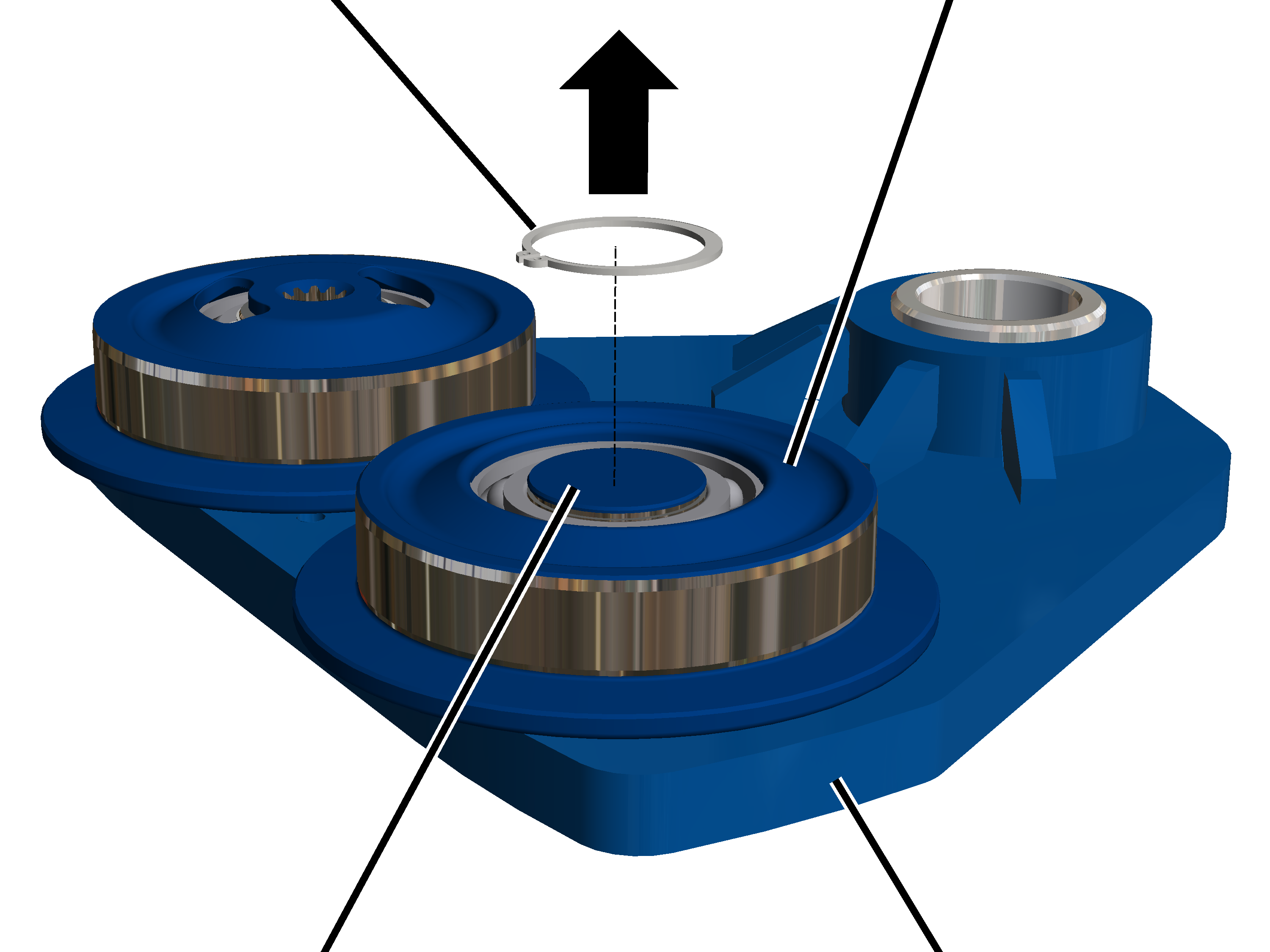
|
Circlip |
Wheel |
|
| |
|
Bolt |
Side panel |
Lay the
side panel on an even surface with wheels facing upward.
Remove the circlips (2x) from
the inner wheels (2x) using pliers.
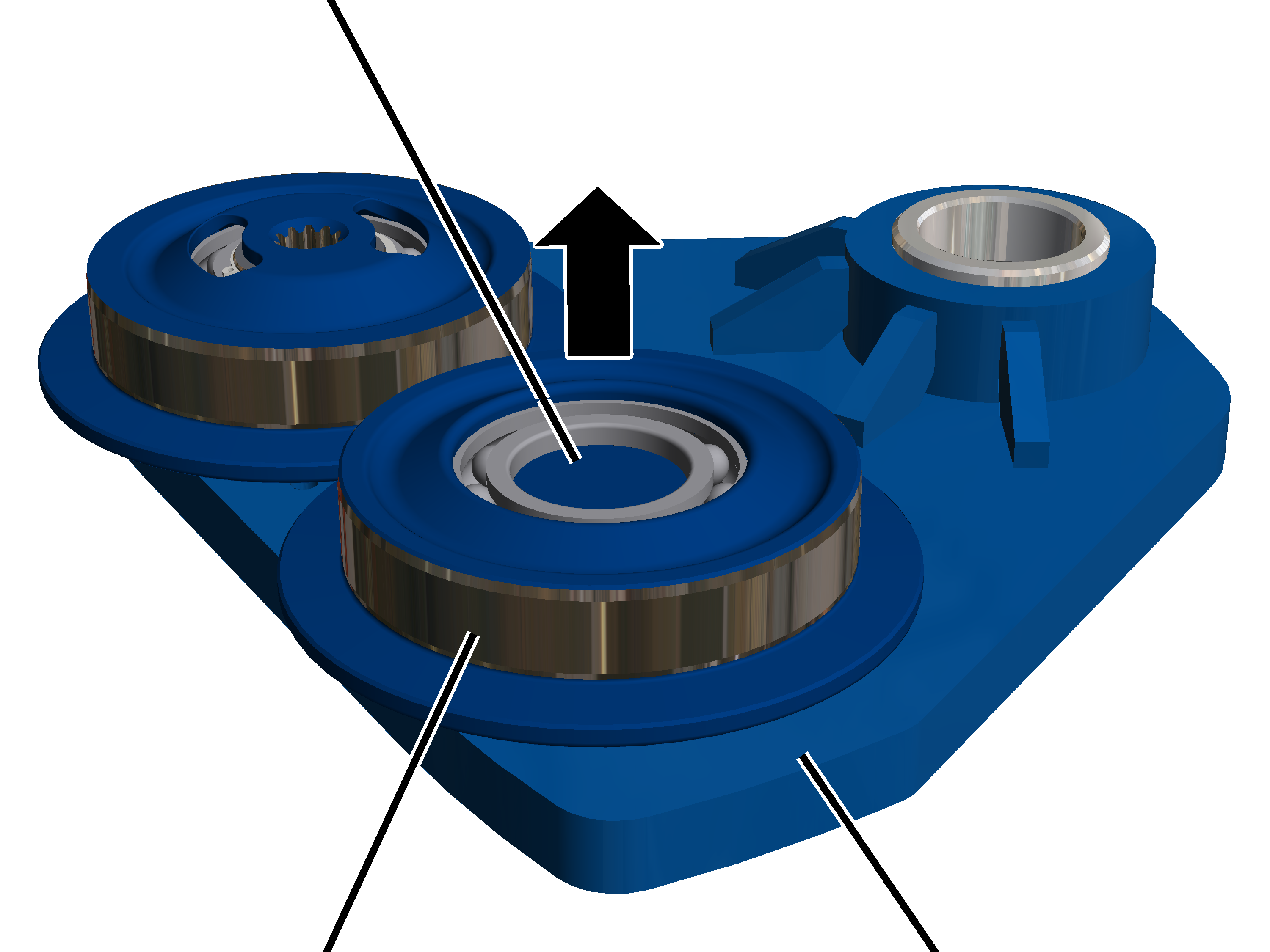
|
Bolt |
|
|
| |
|
Wheel |
Side panel |
Remove the
wheels (2x) from the bolts with a suitable tool.