|
|
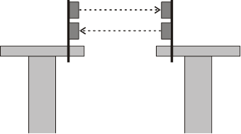
─ The light barriers for transmitting the release signal are installed on opposite ends of the end carriages of the cranes.
─ One transmitter and one receiver is installed on each crane.
─ On one crane, the transmitter is installed at the top and the receiver at the bottom. This is reversed on the other crane.
|
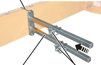
Threaded bracket |
|
|
| |
|
Mount |
Pipe clamp |
 Attach the mount to
opposite ends of the end carriages.
Attach the mount to
opposite ends of the end carriages.
Bolt the mount onto the threaded bracket.
|
Threaded bracket |
Tightening torque |
|
M8 |
25 Nm |
|
M10 |
50 Nm |
|
M12 |
75 Nm |
Slide on the two pipe
clamps and secure them.
|
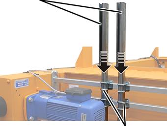
Mount for the light barriers |
|
|
| |
|
|
Pipe clamps |
Push the mount for the
light barriers (2x) into the pipe clamps.
Only where there is a low
installation height (distance from the running surface of the wheel to the upper
edge of the trolley): Push in two additional mounts for light barriers and
secure using pipe clamps (4x).
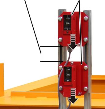
Leave a gap of 250 mm between the two mounts on the left and the two mounts on the right.
Since there is little space above the main girder where crane installation height is low, the light barriers are not installed above one another but rather next to one another using additional mounts.
Align the mounts and
hand-tighten the pipe clamps.
|
Gap between light barriers |
Light barrier |
|
| |
Push the light barriers
into the mounts: First the transmitter, then the receiver.
Align the light barriers.
There must be a gap of 250 mm between the light barriers. Otherwise the
light barriers from the other crane can cause interference, since the light beam
is radiated slightly cone-shaped.
Screw the light barriers
until hand-tight.
Route the light barrier
connection cables to the crane panel and secure with cable clips.