If the wire rope hoist has not been installed yet, continue here. Otherwise, skip this section.
If a GM 800 hoist drive is installed on the wire rope hoist, the wire rope hoist only has one side frame with supporting wheels. Otherwise, the wire rope hoist has two side frames with supporting wheels, which are mounted on a rocker.
In the following, the assembly is shown on a wire rope hoist with two side frames. The assembly with one side frame does not differ significantly.
|
|
 Sling the wire rope hoist and
lift it, e.g. with a truck-mounted crane.
Sling the wire rope hoist and
lift it, e.g. with a truck-mounted crane.
Remove the transport
supports.
|
|
Wire rope hoist |
|
| |
|
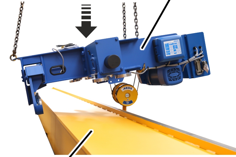
Main girder |
|
Lower the wire rope hoist toward
the main girder.
|
Bracket |
|
|
| |
|
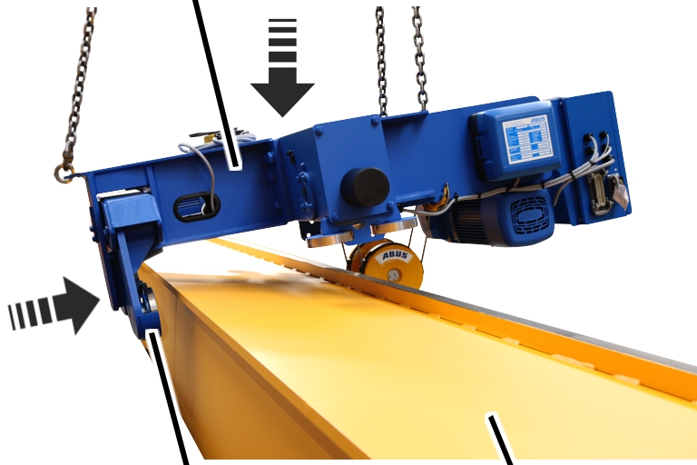
Side frame with supporting wheels |
Main girder |
Press the side frame with
supporting wheels onto the main girder under the upper flange.
Continue lowering the wire rope
hoist.
|
Bracket |
Guide roller |
|
| |
|
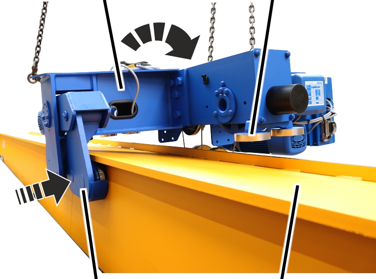
Side frame with supporting wheels |
Upper flange |
Press the side frame with
supporting wheels from below against the upper flange.
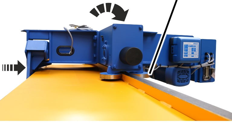
Continue lowering the wire rope
hoist and position the trolley tracks between the guide rollers.
When lowering, ensure that the guide rollers are not damaged and do not impact anything!
|
|
Guide roller |
|
| |
Completely set down the wire
rope hoist.
When lowering, ensure that the guide rollers are not damaged and do not impact anything!
If the wire rope hoist needs to be aligned:
In the following, the alignment is shown on a wire rope hoist with two side frames. The alignment with one side frame does not differ significantly.
|
Rib screw |
Eccentric bolt |
|
| |
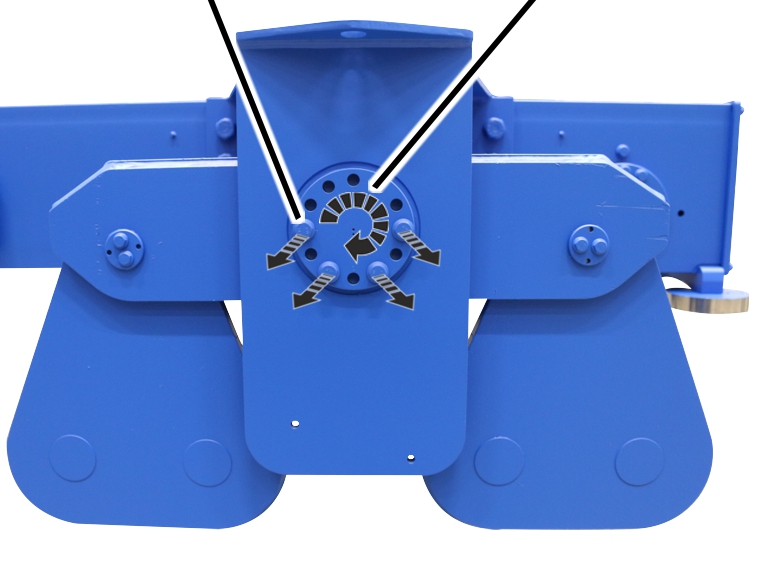
Release the rib screws on the
eccentric bolt.
Align the wire rope hoist
horizontally by turning the eccentric bolt.
|
Rib screw |
Eccentric bolt |
|
| |
Tighten the rib screws on the
eccentric bolt.
|
Size |
Wheel Ø |
Rib screws |
Strength category |
Tightening torque |
|
GM 800 |
160 |
M8x25 |
10.9 |
42 Nm |
|
GM 1000 |
200 |
M10x25 |
10.9 |
75 Nm |
|
GM 2000 |
200 |
M10x25 |
10.9 |
75 Nm |
|
GM 3000 |
200 |
M10x25 |
10.9 |
75 Nm |
|
GM 3000 |
280 |
M12x25 |
10.9 |
115 Nm |
On both sides of the trolley frame:
|
Rib screw |
|
|
| |
|
Lift-off prevention device |
Upper flange |
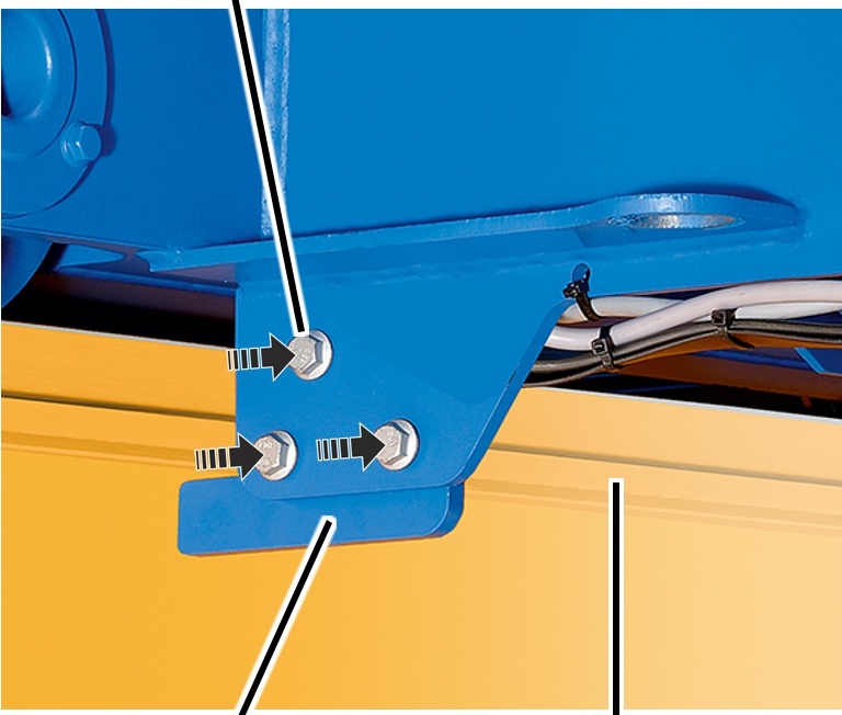
Hold the lift-off prevention
device to the trolley frame.
Screw on the lift-off protection
device tightly with rib screws (3x).
|
Rib screw |
Tightening torque |
|
M12x30 |
115 Nm |
|
M16x35 |
210 Nm |