Only with monitoring of the total load
When a total load is to be monitored, the values of the respective “other” hoist must either be entered or measured as well on both hoists so that these can be saved in the respective LIS-SV.
The following parameters are used to measure the respective “other” hoist:
─ In parameter P 1.1 and P 1.2 the value for the device's own hoist is measured.
─ In the parameters P 2.1 and P 2.2 the values of the respective “other” hoist are measured and saved.
The following parameters are used to enter the values of the respective “other” hoist:
─ The measured values under parameters P 1.1 and P 1.2 can be read under parameter P 1.3 or P 1.4 in the respective device's own hoist.
─ In the parameters P 2.3 and P 2.4 the values of the respective “other” hoist are measured and saved.
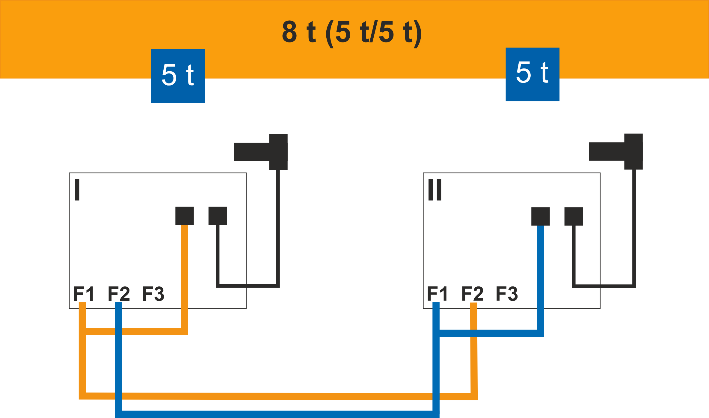
Entering values for other hoists
 Check the assignment according
to the wiring diagram and the carry out the parameterisation according to the
input assignment.
Check the assignment according
to the wiring diagram and the carry out the parameterisation according to the
input assignment.
|
|
|
Designation |
Parameter |
Trolley I ■ |
Trolley II ■ |
|
Maximum load capacity of the total load |
P 0.0 |
8 |
8 |
|
Maximum load capacity of the trolley at input F1 |
P 1.0 |
5 |
5 |
|
Maximum load capacity of the trolley at input F2 |
P 2.0 |
5 |
5 |
|
Switching point of the overload protection of the total load |
P 4.0 |
110 |
110 |
|
Switching point of the overload protection at input F1 |
P 4.1 |
110 |
110 |
|
Switching point of the overload protection at input F2 |
P 4.2 |
110 |
110 |
|
Zero point adjustment at input F1 |
P 1.1 |
0.638 |
0.873 |
|
Setting with test load, trolley I |
P 1.2 |
5.187 |
8.000 |
|
Zero point frequency at input F2 |
P 2.3 |
0.873 |
0.638 |
|
Gain factor at input F2 |
P 2.4 |
8.000 |
5.187 |