|
|
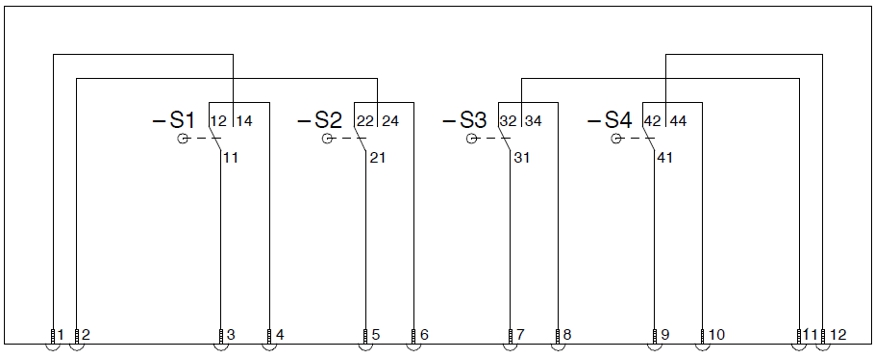
─ The contact numbering shown on the wiring diagram starts on the left ascending from 1.
─ The designation of the microswitches starts on the left of the installation position with S1.
|
Position arrow |
Switch position |
S1 closed |
S1 open |
S2 closed |
S2 open |
S3 closed |
S3 open |
S4 closed |
S4 open |
|
0 |
0° |
3.4 |
|
5.6 |
|
7.8 |
|
9.10 |
|
|
1 |
90° |
3.4 |
|
5.6 |
|
|
7.11 |
9.10 |
|
|
2 |
180° |
3.4 |
|
5.6 |
|
|
7.11 |
|
9.12 |
|
3 |
270° |
|
3.1 |
5.6 |
|
7.8 |
|
|
9.12 |
|
4 |
360° |
|
3.1 |
|
5.2 |
7.8 |
|
9.10 |
|
|
5 |
450° |
3.4 |
|
|
5.2 |
7.8 |
|
9.10 |
|
|
0 |
540° |
3.4 |
|
5.6 |
|
7.8 |
|
9.10 |
|