The figures show the installation of an aluminium HB profile rail of size HB150A. The installation of larger or smaller HB profile rails does not differ significantly from this.
Depending on the length of the individual profile rail sections, the number of suspensions, the on-site building conditions and the length of the crane track, several profile rail sections should be connected with each other on the floor if possible.
The connected profile rail sections must be able to be raised and brought underneath the suspensions safely and without posing additional hazards.
If this is not possible, the profile rail sections must first be fixed individually or as sections on the suspension and then afterward fully joined with each other. When doing this, it must be ensured that there is adequate space underneath the suspensions, especially in the case of short suspensions.
|
|
The figures show the installation of an aluminium HB profile rail of size HB150A. The installation of larger or smaller HB profile rails does not differ significantly from this. |
 The profile rail sections must be laid out on the building floor the
way they are to be later installed.
The profile rail sections must be laid out on the building floor the
way they are to be later installed.
|
|
The position of the profile rail sections is specified in the planning documents. |
The specified dimensions, positions and clearances must be followed exactly.
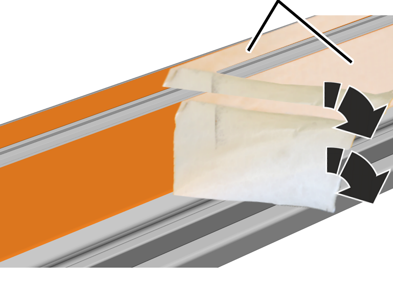
The profile rail sections are laminated at the sides. The protective film is removed before further assembly.
|
|
Protective film |
|
| |
 Pull off the protective film at a sharp angle from the side
lamination.
Pull off the protective film at a sharp angle from the side
lamination.
|
|
Head nut |
|
| |
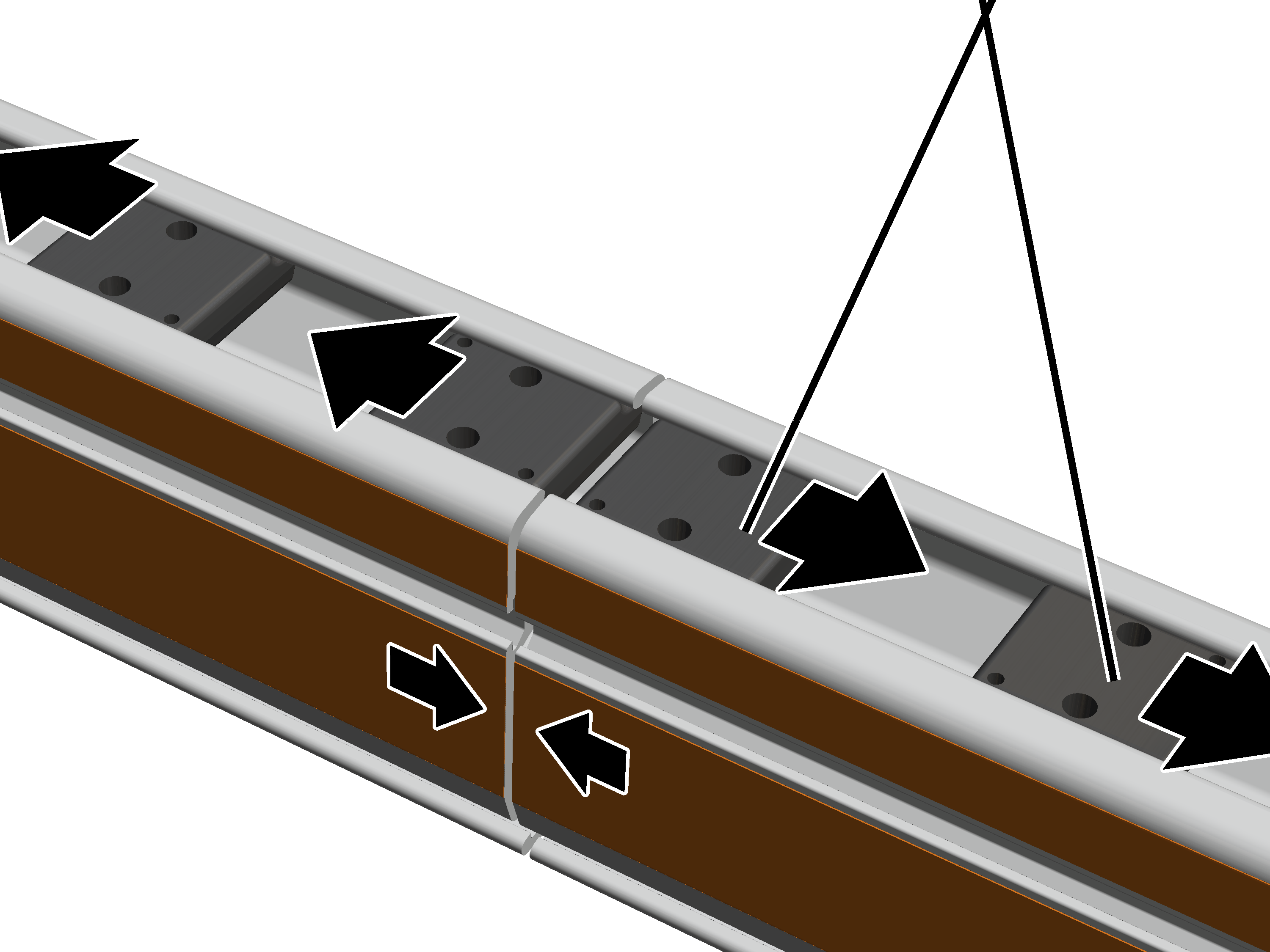
Insert two head nuts each in the left and right profile rail
sections.
In the case of connection with one curved section: only one head nut each is inserted into the left and right profile rail section.
Lay the profile rail sections to one another.
The profile rail sections can be directly flush to one another. The must not be more than 2 mm apart.
This work step only applies if a suspension will be installed in the area of a profile joint.
Before the clamping plates are inserted:
|
Profile joint |
Bearing shell |
|
| |
|
|
Profile link |
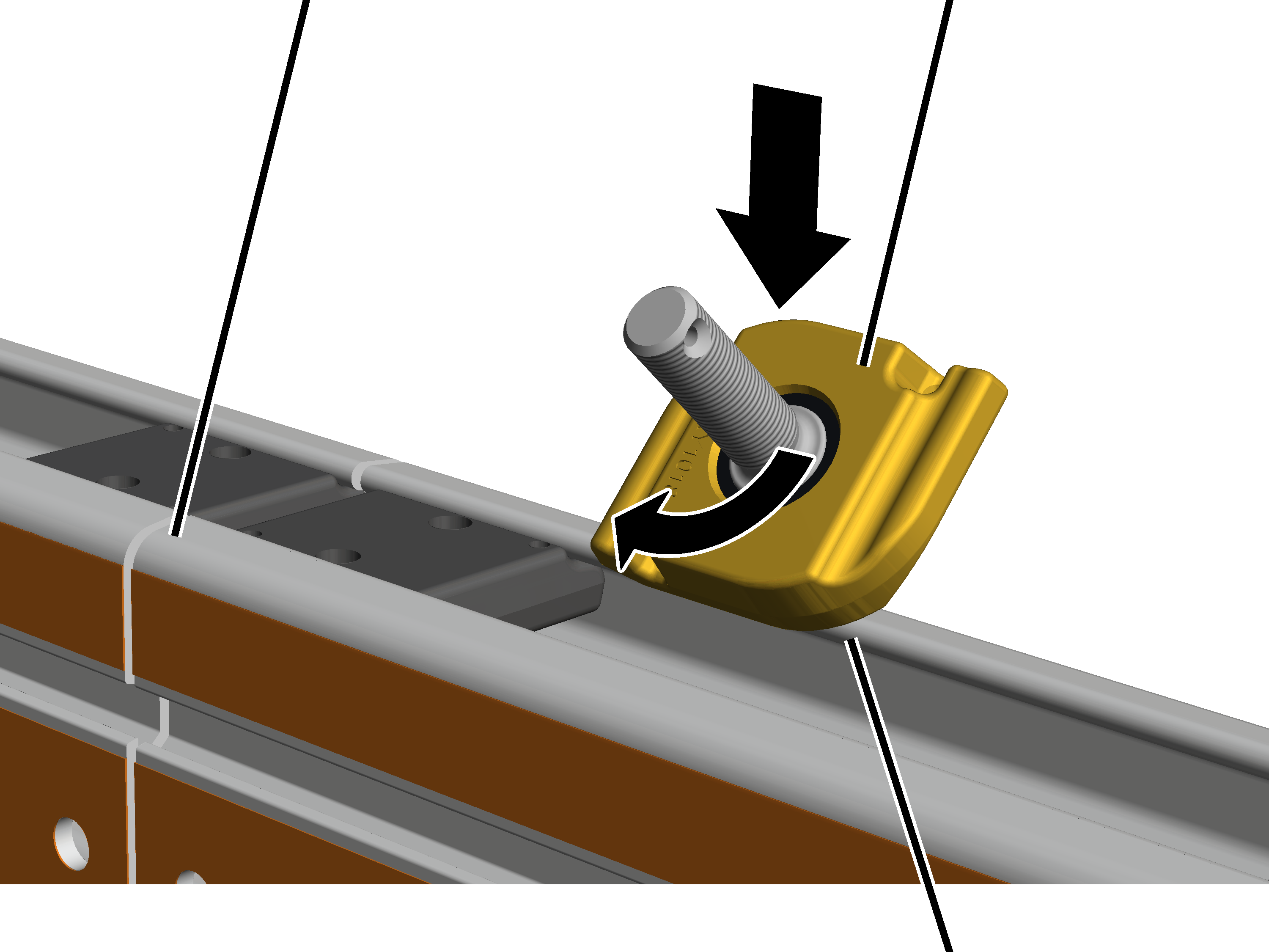
Tilt the profile link and insert it from above at the required point
in the profile head.
Once the clamping plate is installed, the profile link can no longer be shifted at will.
The bearing shell in the ceiling-mounted bracket and on the profile link must always have the same colouring (silver or yellowish). Ceiling-mounted brackets and profile links with differently coloured bearing shells must not be installed together.
Turn the profile link 90 degrees.
|
Clamping plates |
|
|
| |
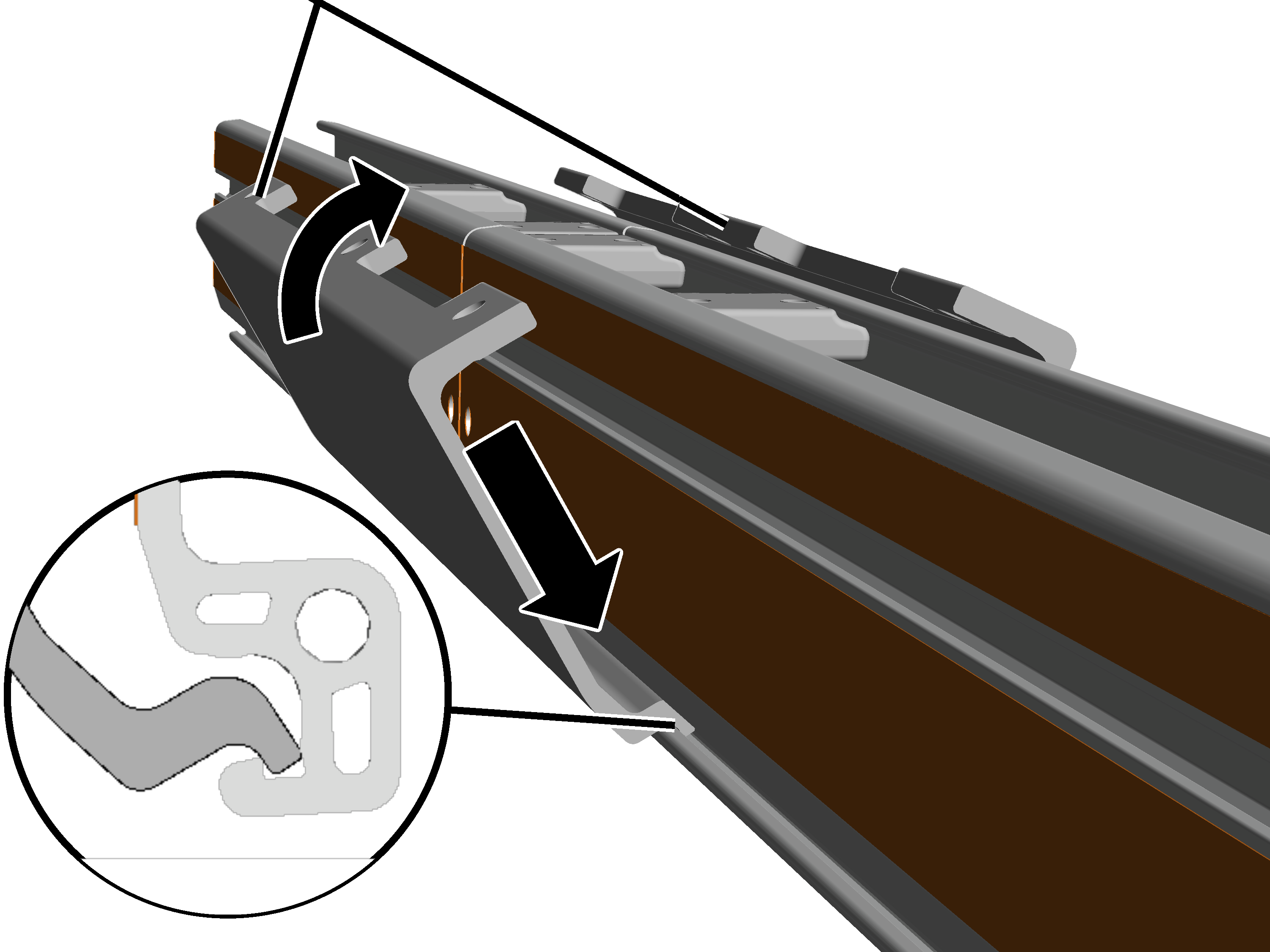
Tilt the clamping plate slightly and insert it below in the profile
rail section.
When doing this, insert the bottom of the clamping plate behind the edge on the profile rail section.
Position the clamping plate so that it is exactly centred between the
two profile rail sections.
Press the clamping plate together at the top.
● At the bottom the clamping plate presses from the inside against the edge of the profile rail section.
This work step only applies if a suspension will be installed in the area of a profile joint.
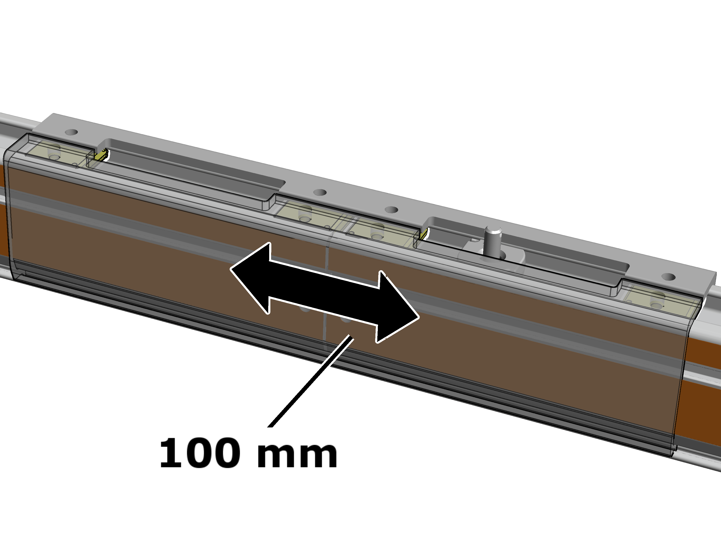
Only with a craneway suspension in the area of a clamping plate: the clamping plates do not need to be inserted exactly centred on the profile joint. The clamping plates can be shifted up to 100 mm to the left or right so that the profile link for the suspension is always at the preferred point.
Note:
For a profile joint without a suspension, the clamping plates must be installed exactly centred!
|
|
Only with a craneway suspension in the area of a clamping plate: the
clamping plates can be shifted up to 100 mm.
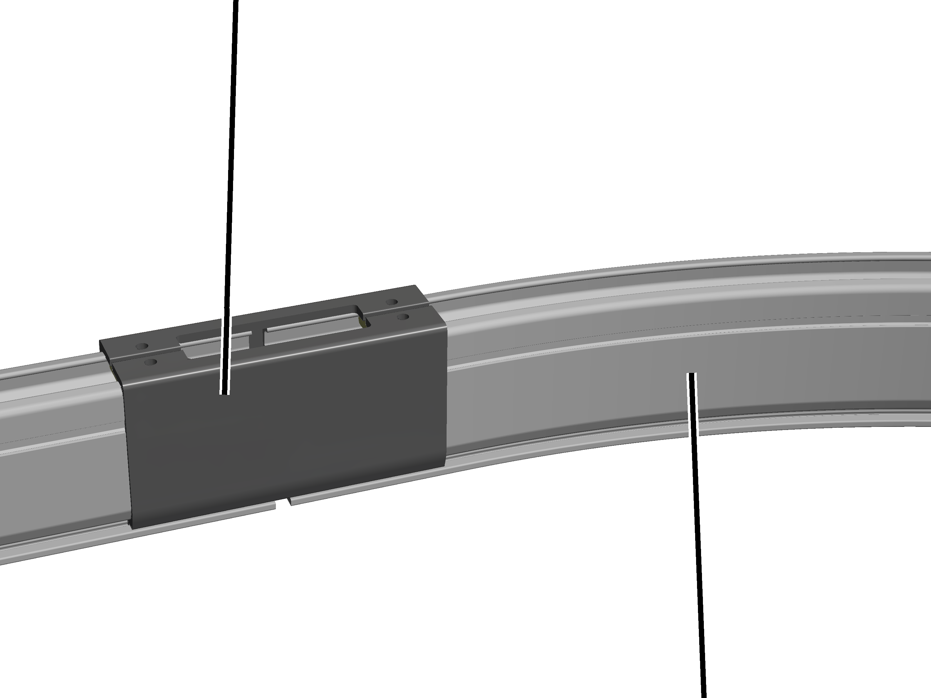
This work step only applies if an HB profile rail is to be installed as a curved section.
|
Clamping plate |
|
|
| |
|
|
Curved section |
Slide the short clamping plate on the curved section in such a way
that it is exactly in the centre. It must not be displaced sideways.
Check the spacing of the profile rail sections again.
The profile rail sections can be directly flush to one another. The must not be more than 2 mm apart.
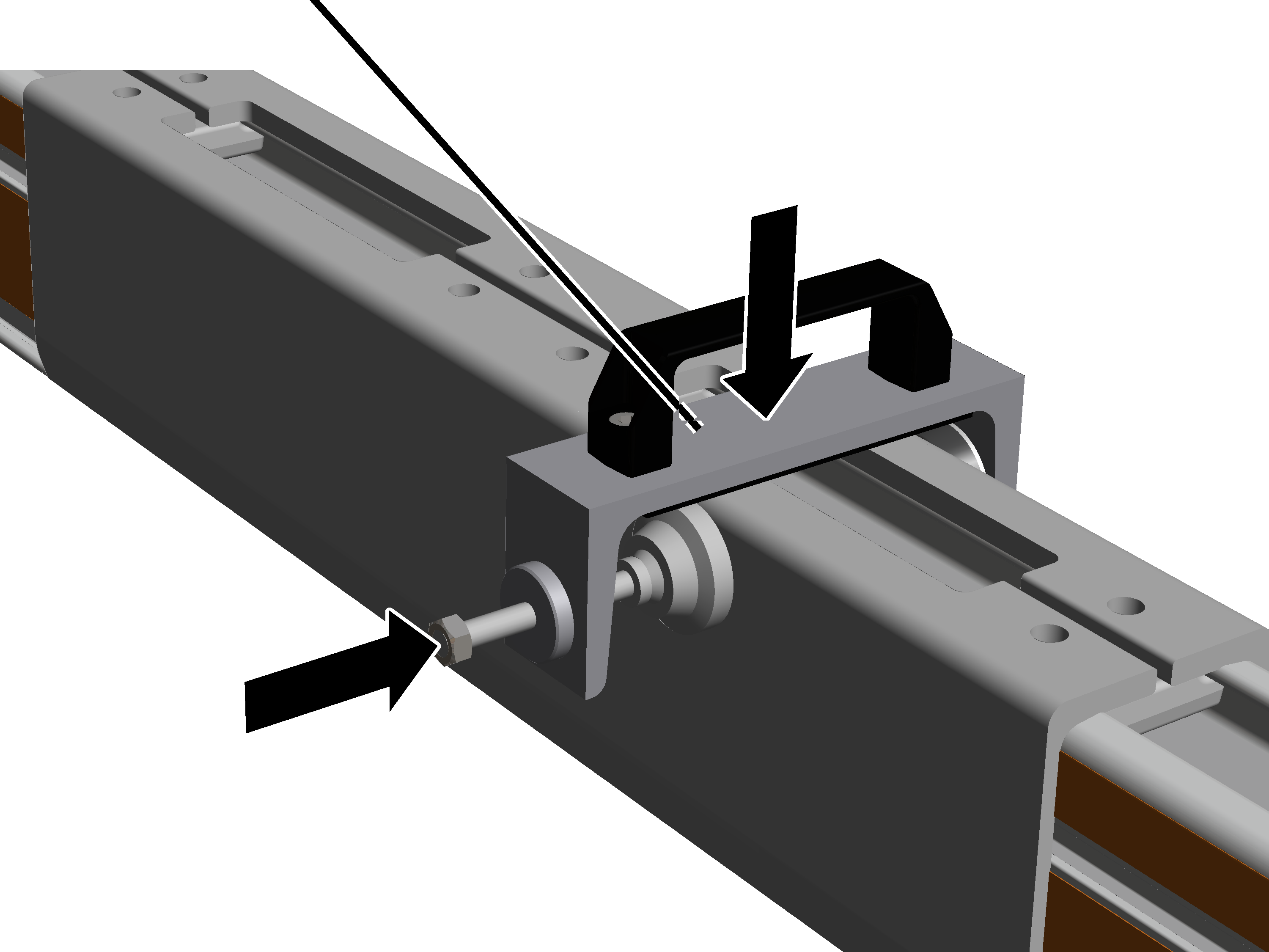
|
Assembly aid |
|
|
| |
Press the clamping plates together to such an extent that the
assembly aid can be set in place.
Place the assembly aid on the clamping plate.
The assembly aid can be obtained from ABUS Service. AN 316469.
Alternatively, a screw clamp with suitable base (e.g. rubber mat) can be used.
Screw the assembly aids together until the clamping plates can
clearly be heard to latch into place at the sides.
The clamping plates must be clearly heard to latch in place on both sides and at both profile rail sections.
If necessary: use the assembly aid to press the clamping plates together at the other end as well until they can clearly be heard to latch into place.
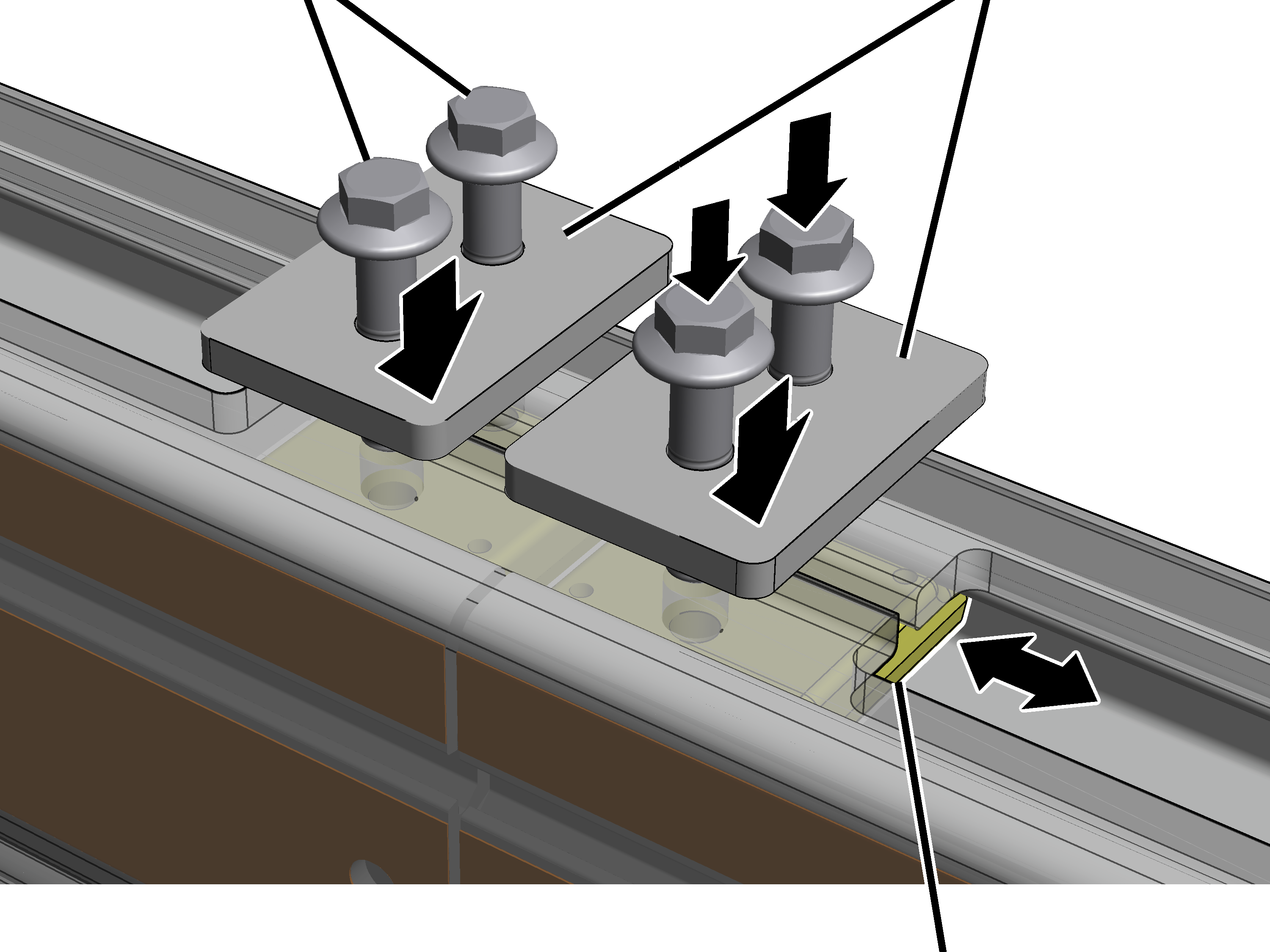
At all four head nuts:
|
Rib screw M12x50 |
Metal plate |
|
| |
|
|
Head nut |
Position the head nut until it is exactly underneath the clamping
plate bracket.
Place the plate on the drilled holes in the clamping plate.
Insert the rib screws M12x50 (2x per profile holder) through the
plate and the clamping plate and screw into the head nut.
Screw in the rib screws. 130 Nm.