The following requirements must be
met in order for the HB crane installation to be installed:
Checking the
requirements through a technical pre-clarification
The requirements for assembly of the HB crane installation
can be checked by ABUS through a technical pre-clarification.
─ The
technical pre-clarification is in any case performed if the assembly of the HB
crane installation is done by ABUS.
─ The
technical pre-clarification can also be performed by ABUS if the HB crane
installation is done autonomously or through other fitting and installation
companies.
─ If no
technical pre-clarification is performed by ABUS, the following requirements
must be independently checked and documented prior to the installation.
─ The
supporting structure (building, hall ceiling, building support, etc.) must be
able to withstand the expected loads.
─ There
must be adequate space on the supporting structure for the ceiling connection.
Other parts such as lamps, piping, vents, heaters should not interfere with the
installation of the ceiling connection.
If parts that interfere are present, these must be taken into
account during the planning of the HB crane installation. In this case, special
craneway suspensions are necessary (e.g. V-suspension) in order to evade the
interfering parts or the interfering parts must be removed or the craneway
suspension planned around these parts.
Checking the
planning documents
─ All
planning documents for the HB crane installation must be present.
ABUS creates and calculates these planning documents separately
for each individual HB crane installation (or for the reconstruction of an
existing HB crane installation).
The planning documents consist of at least a layout plan, an
assembly plan and an overview of the suspensions and ceiling connections.
The planning documents, especially the suspension distances and
projections, must in any case be followed exactly.
Only with ceiling connection
using anchor connection
 Have concrete elements (e.g.
intermediate deck) checked by a structural engineer.
Have concrete elements (e.g.
intermediate deck) checked by a structural engineer.
In doing so, observe at least the following points:
─ The
concrete element must be of sufficient thickness.
─ The
quality of the concrete must be adequate.
─ The
reinforcement cage in the concrete elements should not be damaged during
assembly work. If this cannot be ensured, any damage to the reinforcement cage
should not negatively affect the structural characteristics.
─ The
concrete element may be maximally 400 mm in thickness.
Check the top side of the concrete
element (e.g. floor of the next story above).
In doing so, observe at least the following points:
─ The top
side may not be covered with anything (e.g. tiles) that cannot withstand the
loads.
─ The
counter plates of the cup square bolts should not protrude.
Only with ceiling connection
using dowel plate
─ The
concrete ceiling must have at least quality B25 (C20/25) and maximally B55
(C50/60).
─ The
concrete ceiling must be able to withstand the expected loads produced by the HB
crane installation.
─ The
concrete ceiling must be at least as thick as specified in the table. The
minimum clearance of the drilled holes to joints and edges must be observed.
|
Highbond dynamic anchors |
Minimum thickness of the concrete ceiling |
Minimum clearance to joints and edges |
|
M12 |
140 mm |
150 mm |
|
M16 |
160 mm |
150 mm |
Performing the
technical pre-clarification for the installation of the dowel plate
Perform the separate technical
pre-clarification for the installation of the dowel plate using anchor rod and
injection mortar.
See “Technical pre-clarification and requirements for dowel
fastenings of ABUS suspended rail systems”
Only with normal
suspension
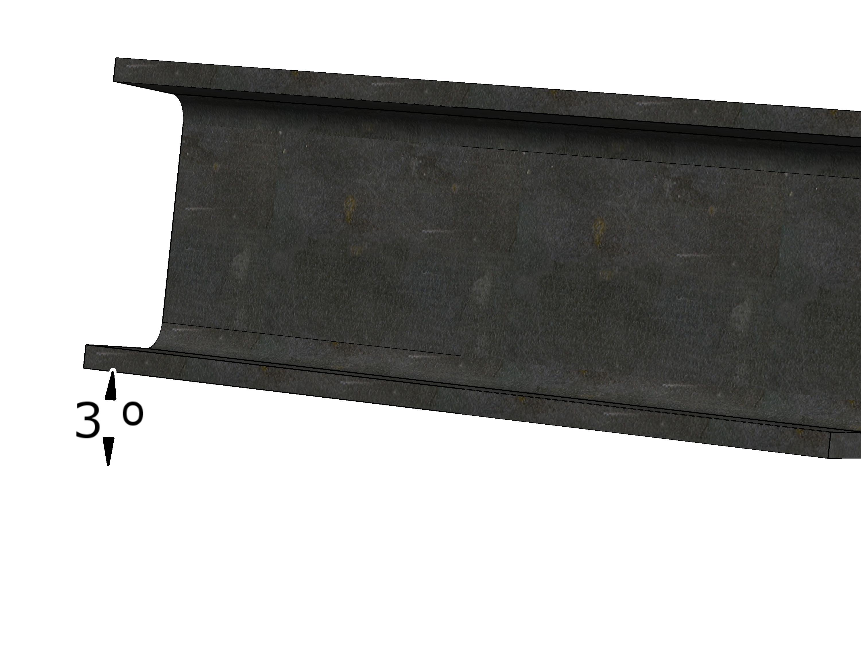
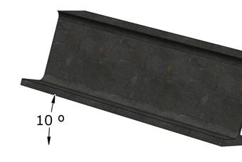
Checking the
incline of the supporting structure for normal suspensions
Check the incline of the supporting
structure.
The incline for normal suspensions may be maximally 3° in
all directions.
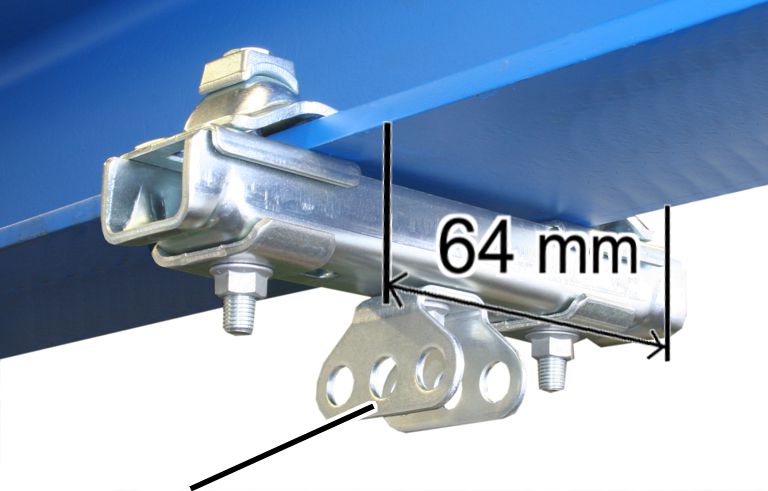
Checking the
flange width
Only with ceiling-mounted
brackets 2LP/M16 or M20 with threaded rod
|

|
|
Ceiling-mounted brackets 2LP/M16 or M20 with threaded
rod |
|
Check the flange width on the I-beam
of the supporting structure.
The flange must be at least 64 mm wide.
Only with ceiling-mounted
bracket 2LP/M16 with articulated girder in longitudinal direction
|
|
|
Ceiling-mounted bracket 2LP/M16 with articulated girder in
longitudinal direction |
|
Check the flange width on the I-beam
of the supporting structure.
The flange must be at least 64 mm wide.
Only with ceiling-mounted
bracket 2LP/M16 with articulated girder in crosswise direction
|

|
|
Ceiling-mounted bracket 2LP/M16 with articulated girder in
crosswise direction |
|
Check the flange width on the I-beam
of the supporting structure.
The flange must be at least 80 mm wide.
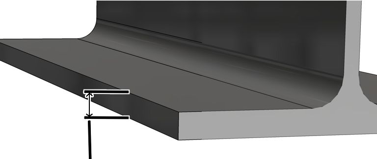
Only with ceiling connection
using flange clamp
|
|
|
Flange
thickness |
|
Check the flange thickness on the
I-beam of the supporting structure.
The flange thickness must be between 6 and 20 mm.
If the flange is thicker than 20 mm:
special retaining plates must be used in the assembly.