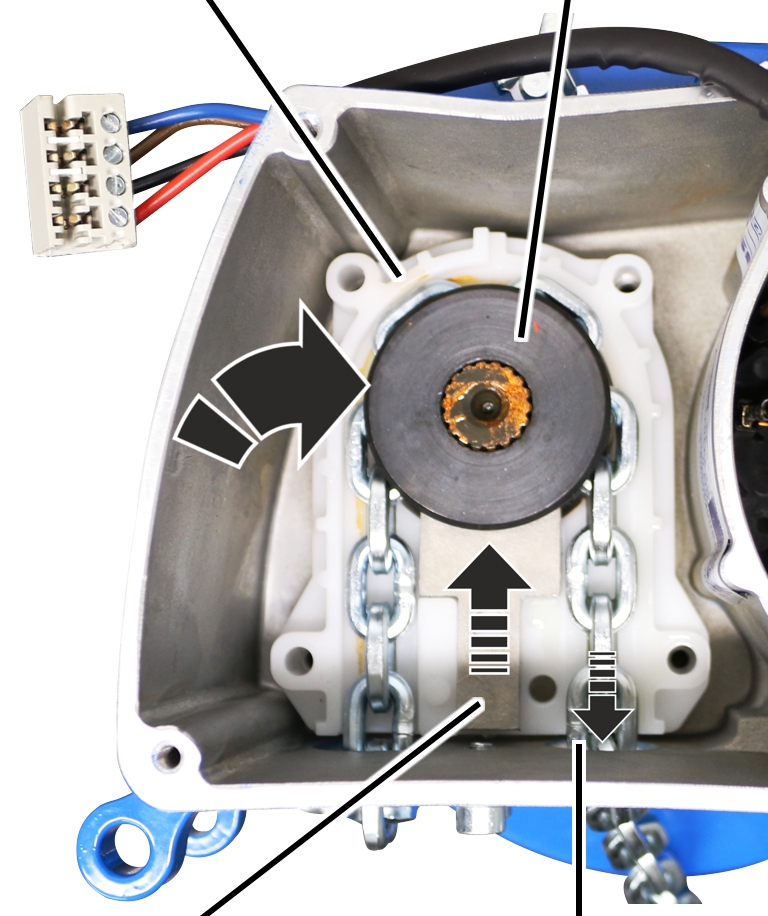
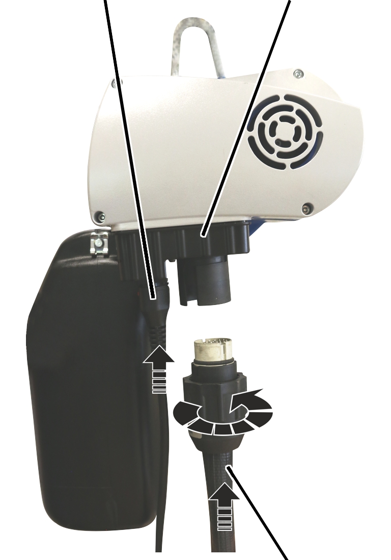
Connection cable
Socket
Control cable with bayonet connector and bayonet nut
If the chain exhibits signs of wear or is too stretched from operation (see Inspecting the chain), it must be exchanged.
Because of the modular construction of the chain hoist, the gear unit does not need to be disassembled in order to exchange the chain guide and chain sprocket. Instead, the motor cover is removed and the chain sprocket is then exposed.
|
Connection cable |
Socket |
|
| |
|
|
Control cable with bayonet connector and bayonet nut |
 Remove bayonet nut of the
control cable.
Remove bayonet nut of the
control cable.
Detach control cable.
|
| |
|
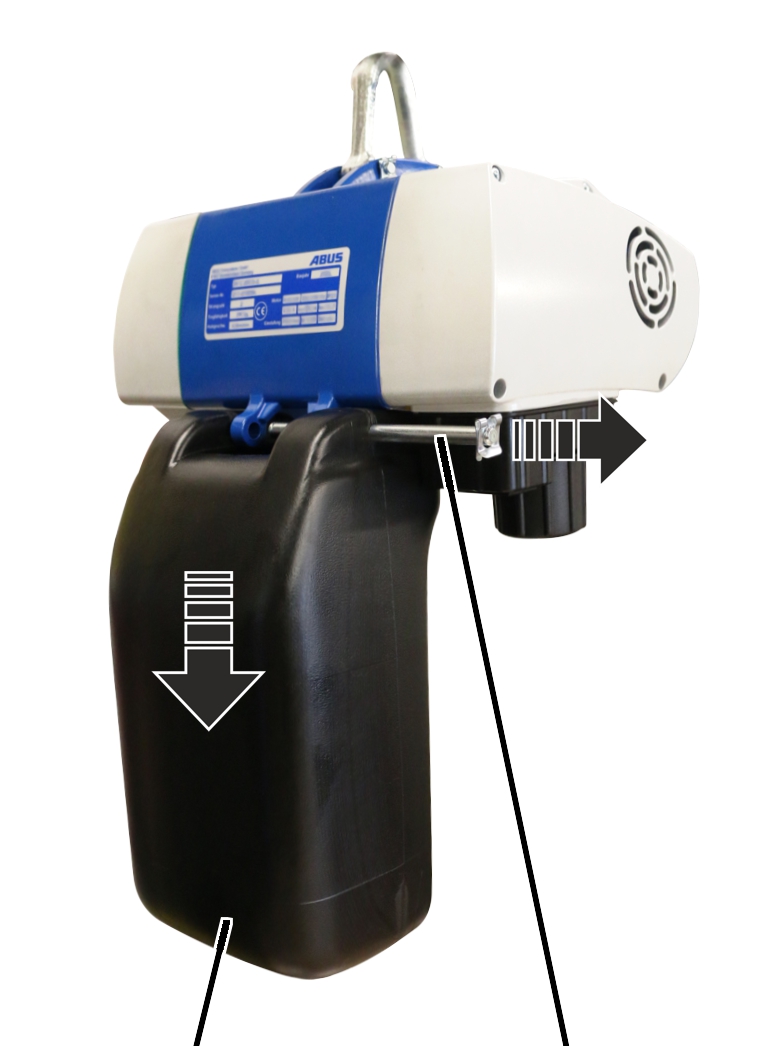
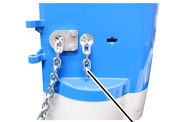
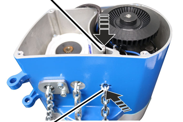
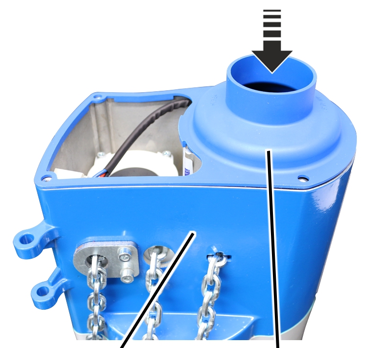
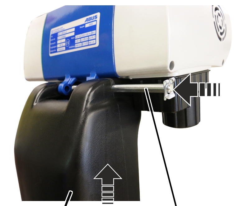
Chain box |
Bolt |
Detach the SL safety clip from
the bolt.
Hold the chain box firmly and
pull out the bolt.
Remove the chain box.
|
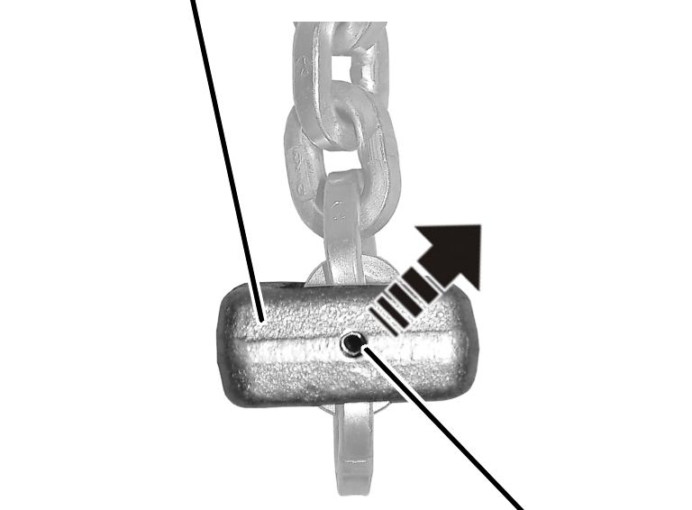
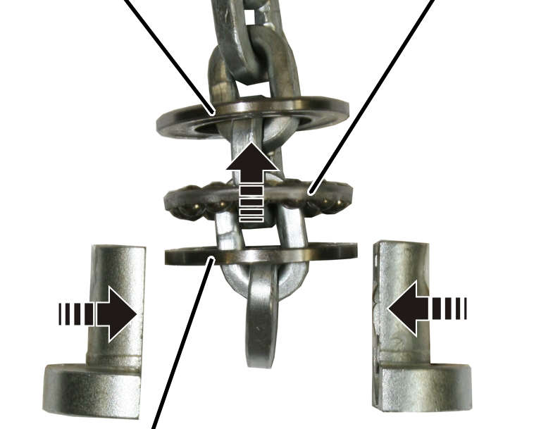
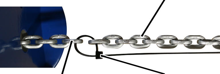
C-link |
|
|
| |
|
|
Tensioner sleeve |
Hammer the tensioner sleeve out
of the C-link.
|
Housing | |
|
| |
|
|
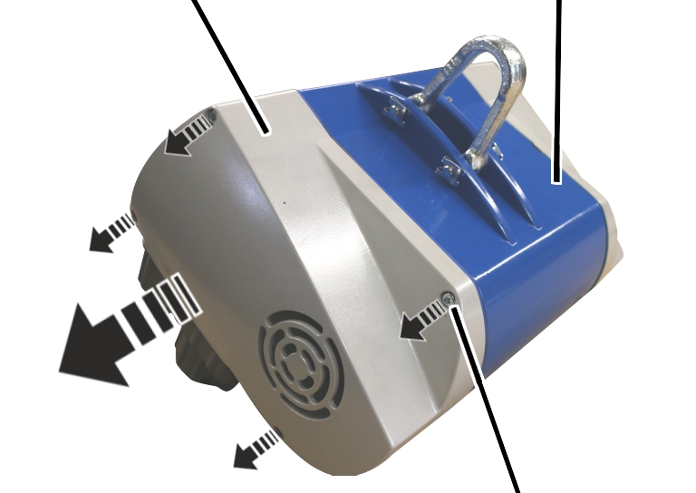
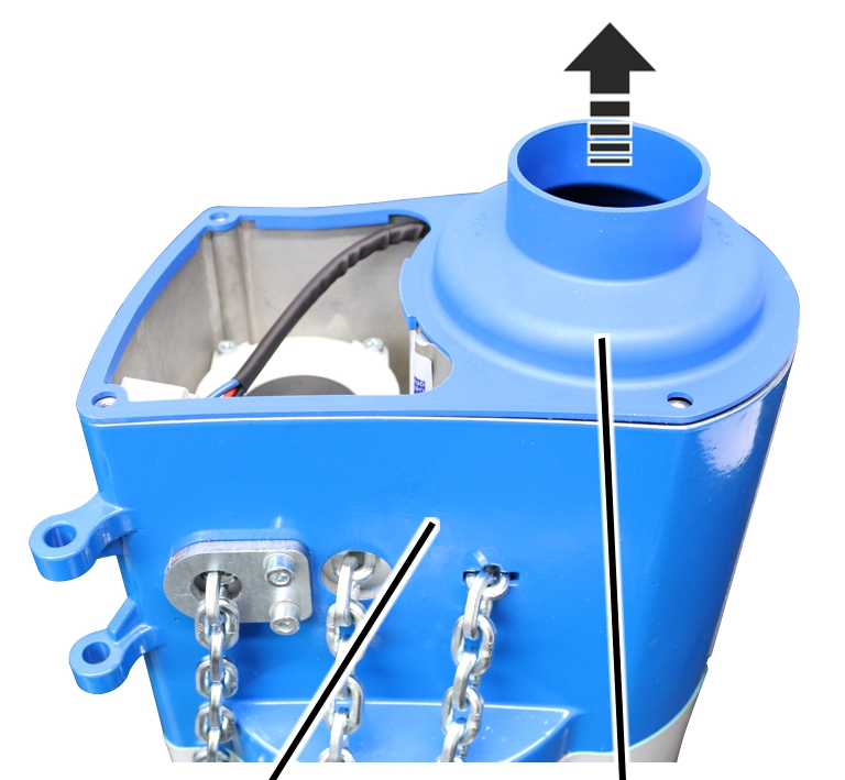
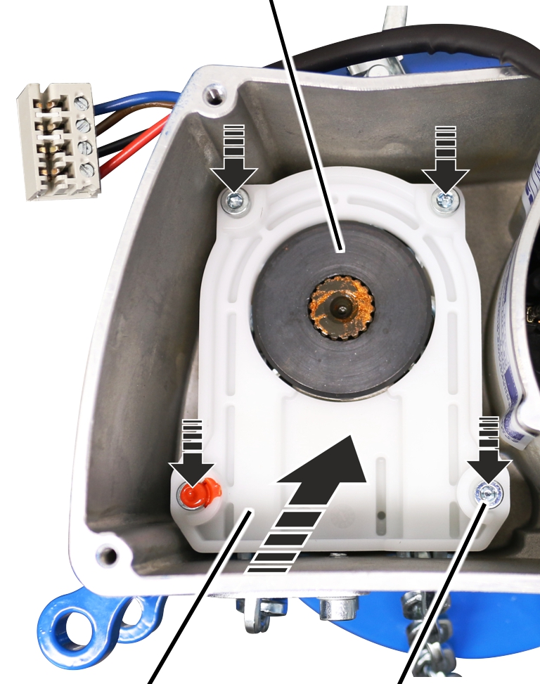
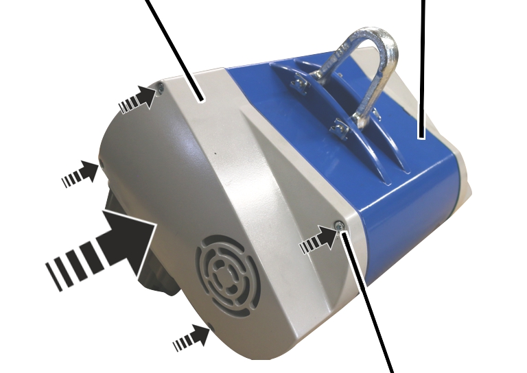
Fillister-head screw |
Unscrew the motor cover from the
housing.
|
|
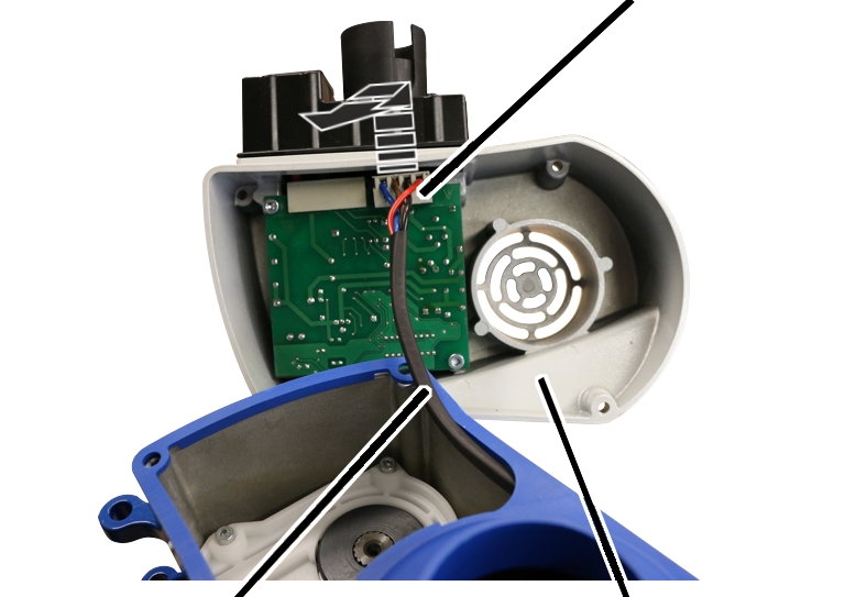
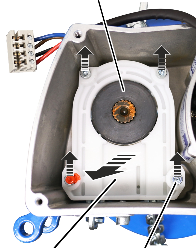
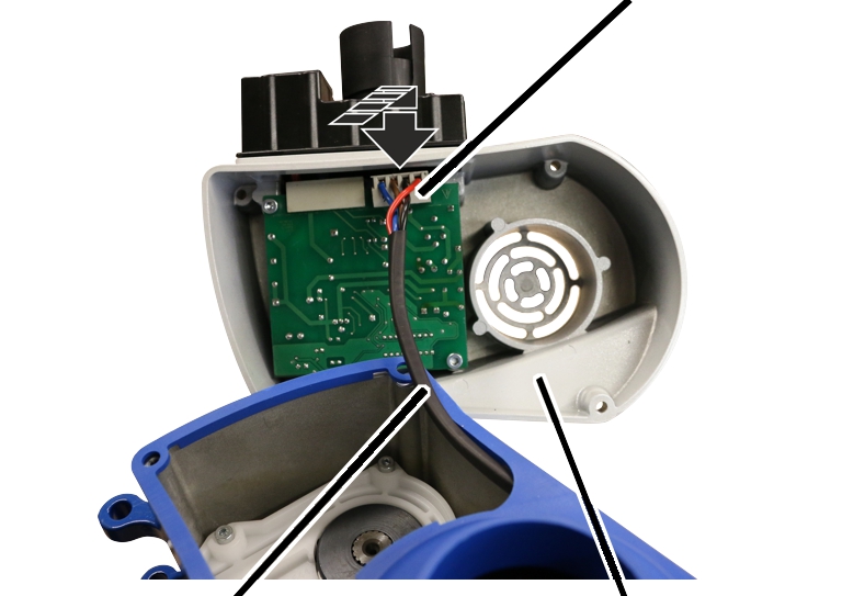
Connector |
|
| |
|
Motor connection cable |
Motor cover |
Unplug the connector of the
motor connection cable from the circuit board.
|
| |
|
Housing |
Seal |
 Remove seal.
|
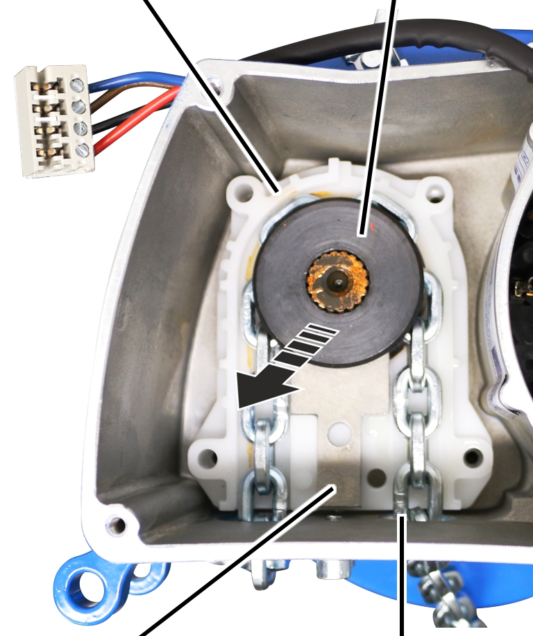
Chain sprocket | |
|
| |
|
Upper half of chain guide |
Screw |
Unscrew the screws (4x) from the
chain guide.
Take out upper half of chain
guide.
|
Lower half of chain guide |
Chain sprocket |
|
| |
|
Axial alignment plate |
Chain |
Remove lower half of the chain
guide with chain sprocket, chain, and axial alignment plate from the
housing.
|
| |
|
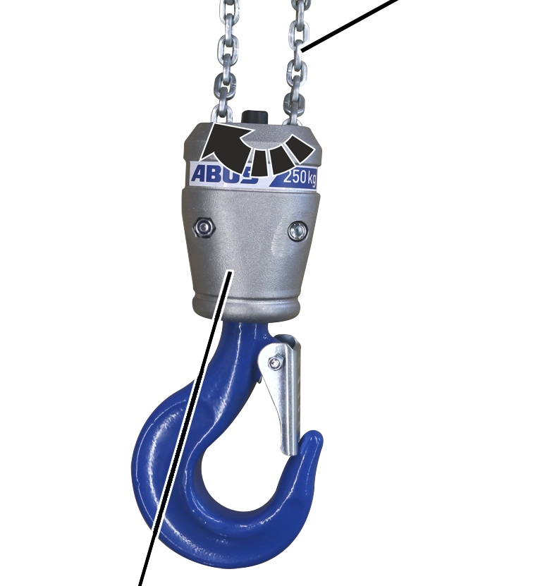
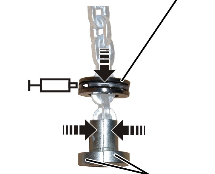
Hook assembly |
|
Screw the hook assembly
apart.
|
| |
|
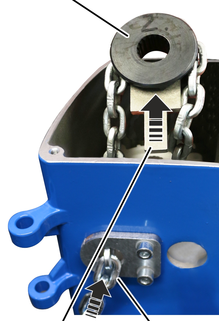
Chain fastening element half |
Deep groove ball thrust bearing |
Push the three-piece deep groove
ball thrust bearing upward.
Remove both chain fastening
element halves from the chain.
Note the layout position of the deep groove ball thrust bearing and remove it from the chain.
|
Cylindrical pin |
|
|
| |
|
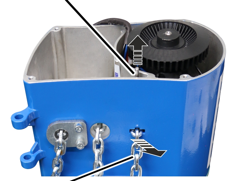
End of 2nd fall |
|
Firmly hold the end of the 2nd fall
and pull out the pin.
● The chain is now released.
|
|
2nd fall of chain |
|
| |
|
Bottom block |
|
Pull the chain out of the bottom
block.
|
Chain sprocket |
|
|
| |
|
Axial alignment plate |
Chain |
Lay lower half of chain guide in
the housing.
Lubricate the new chain
sprocket.
Lubricant: “High-Lub LT1 EP”. For details, see Lubricants.
Pull the new chain through the
left opening in the housing.
Place the new chain around the
chain sprocket.
Push the axial alignment plate
in the chain sprocket.
|
Lower half of chain guide |
Chain sprocket |
|
| |
|
Axial alignment plate |
Chain |
Lay the chain sprocket with
axial alignment plate and chain in the lower half of the chain guide.
Pull the end of the chain out of
the housing through the right opening.
|
Chain sprocket | |
|
| |
|
Upper half of chain guide |
Screw |
Place the upper half of the
chain guide flush on the lower half of the chain guide.
Screw the chain guide tight with
screws (4x). 3 Nm
|
| |
|
|
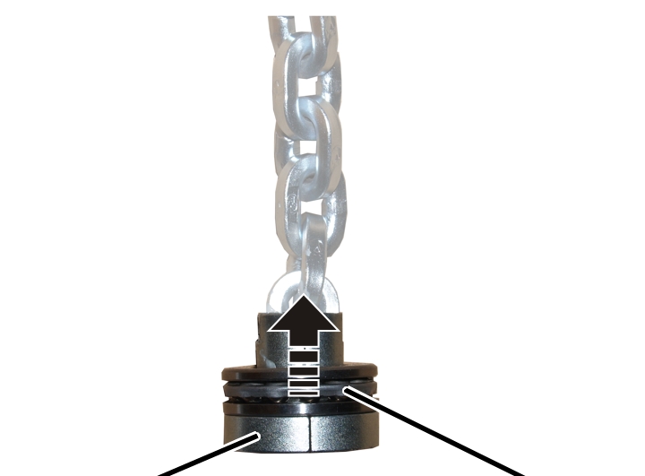
Inside end of chain |
Use the inside end of the chain
to install the load hook.
|
Ball bearing race |
Ball bearing cage |
|
| |
|
Ball bearing race |
|
Push the deep groove ball thrust
bearing onto the chain facing the right direction: First push on the ball
bearing race with the larger inner diameter (smoothed), then the ball bearing
cage, then the ball bearing race with the smaller inner diameter (not
smoothed).
Place the chain fastening
element halves on the chain from both sides.
|
|
Deep groove ball thrust bearing |
|
| |
|
|
Chain fastening element halves |
Push the deep groove ball thrust
bearing over the chain fastening element halves.
Lubricate the deep groove ball
thrust bearing.
Lubricant: “High-Lub LT1 EP”. For details, see Lubricants.
|
|
Deep groove ball thrust bearing with chain fastening element halves |
|
| |
|
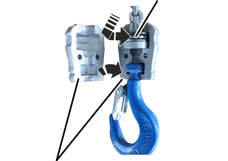
Hook assembly |
|
Insert the deep groove ball
thrust bearing with chain fastening element halves into one half of the hook
assembly.
Assemble the hook assembly.
Bolt the hook assembly with the
fillister-head screw and self-locking nut (2x).
|
2nd fall of chain |
Deflection roller |
|
| |
|
Load hook |
Lower half of bottom block |
Align the 2nd fall of the chain
so it is without any twists.
Place the 2nd fall around the
deflection roller of the bottom block.
The 2nd fall should not be twisted.
|
|
2nd fall of chain |
|
| |
|
Upper half of the bottom block |
Fillister-head screw with self-locking nut |
Place the upper half of the
bottom block flush on the lower half of the bottom block.
Screw the bottom block together
with fillister-head screws (2x) and self-locking nuts. Tighten with
10 Nm.
|
Cylindrical pin |
|
|
| |
|
End of 2nd fall |
|
Push the end of the 2nd fall
into the housing recess on the right.
Hammer in the cylindrical
pin.
● The end of the chain is fixed.
|
If only the chain is to be replaced:
Tip:
Affix cable ties or wire to the end of the old chain and use that to pull the new chain slowly through the chain guide.
| ||||||
|
| |
|
Housing |
Seal |
Press seal flush onto the
housing.
|
|
Connector |
|
| |
|
Motor connection cable |
Motor cover |
Plug the connector of the motor
connection cable into the circuit board in the motor cover.
|
Motor cover |
Housing |
|
| |
|
|
Fillister-head screw |
Hold the motor cover on the
housing.
Screw the motor cover tight with
M4x55 fillister-head screws (3x) and a M4x20 fillister-head screw (1x).
5 Nm.
|
| |
|
| |
|
|
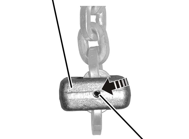
Tensioner sleeve |
Use the outside end of the chain
to install the C-link.
Turn the C-link so that the
opening, when installed, points in the direction of the inner fall (the fall
under load).
Push the C-link onto the
second-last or third-last chain link (depending on the orientation from the
previous step).
Hammer the tensioner sleeve into
the C-link.
Place the chain in the chain
box.
Check whether the chain
completely fits in the chain box. If the chain box is too small, contact ABUS
Service. See ABUS Service.
|
| |
|
Chain box |
Bolt |
Turn the chain box so that it
appears as shown in the figure.
Place the chain in the chain
box.
Use the bolt to install the
chain box on the chain hoist.
|
|
Bolt |
|
| |
|
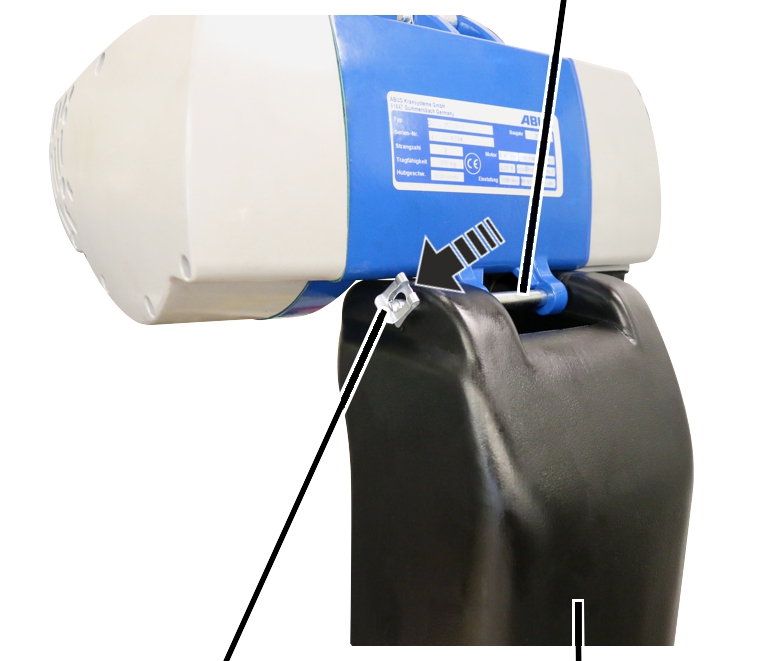
SL safety clip |
Chain box |
Push the SL safety clip onto the
bolt.
Note
If the chain is not adequately lubricated, it must be relubricated. See Lubricating the chain.
|
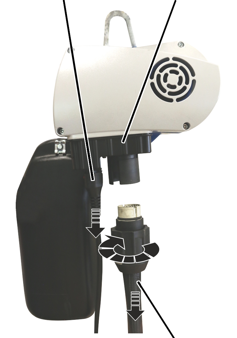
Connection cable |
Socket |
|
| |
|
|
Control cable with bayonet connector and bayonet nut |
Insert the connector of the
connection cable into the chain hoist.
Slide on the bayonet nuts of the
pendant control.
Insert the bayonet connector in
the chain hoist.
Tighten the bayonet nuts of the
pendant control.