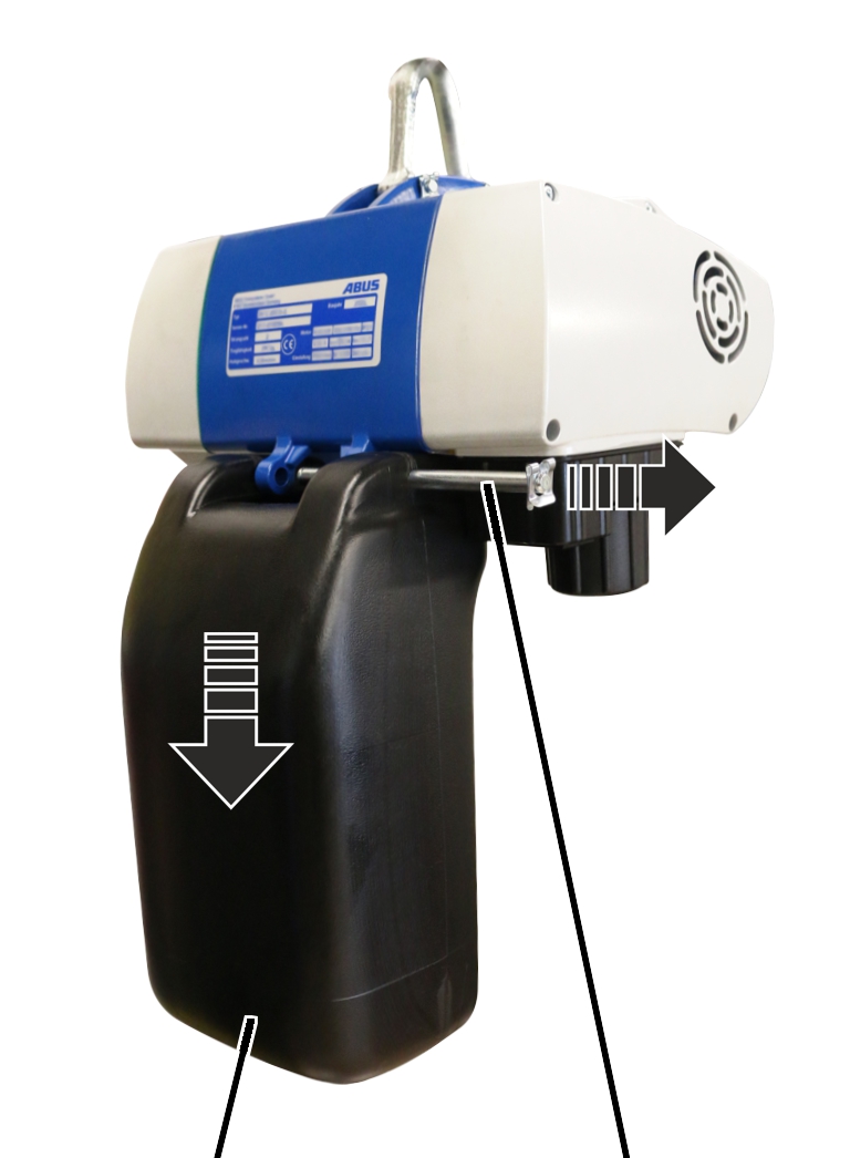
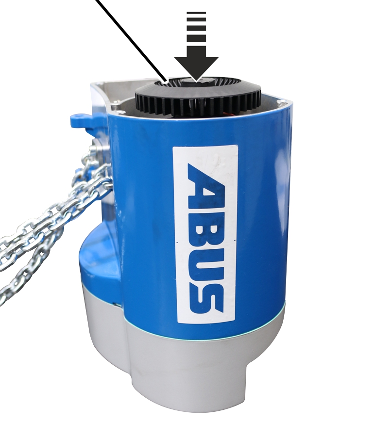
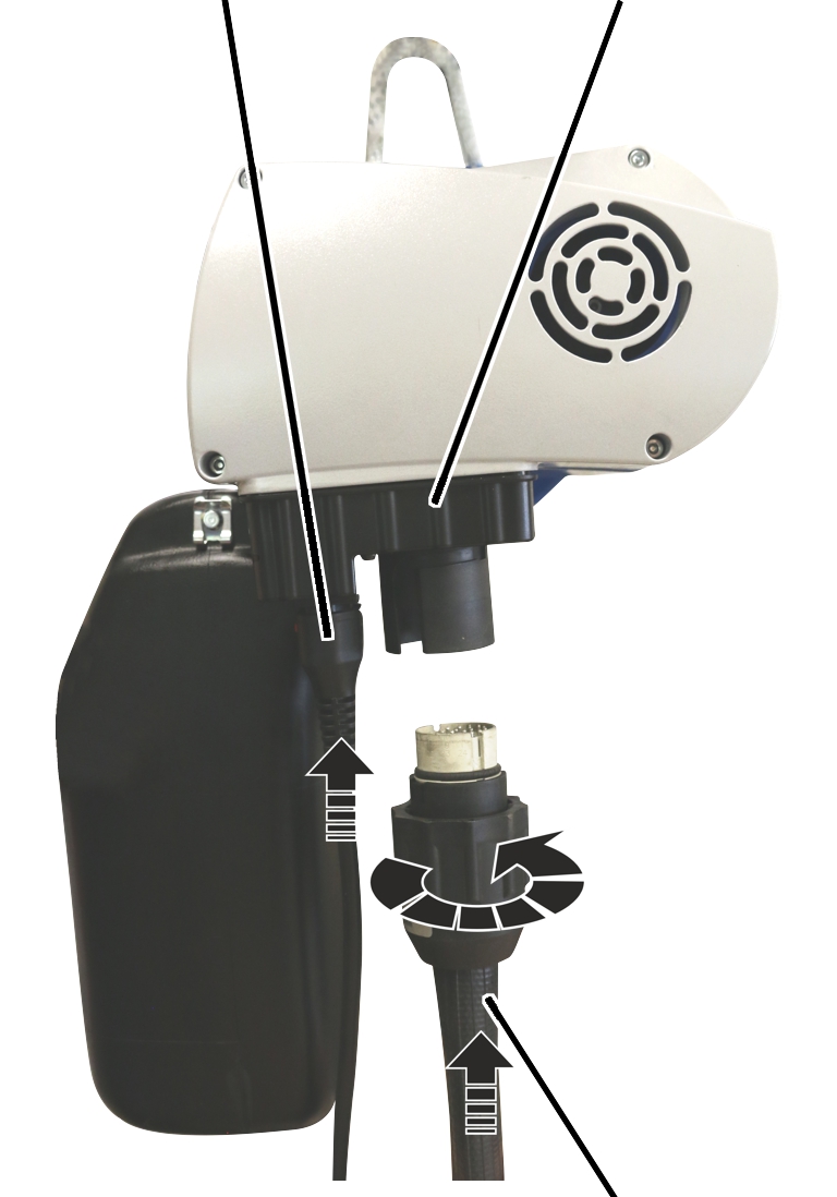
Connection cable
Socket
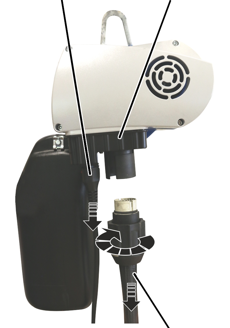
Control cable with bayonet connector and bayonet nut
If the carbon brushes have reached their wear limit, they must be replaced so that trouble-free running of the motor is ensured.
|
Connection cable |
Socket |
|
| |
|
|
Control cable with bayonet connector and bayonet nut |
 Detach connection cable.
Remove bayonet nut of the
control cable.
Detach control cable.
|
| |
|
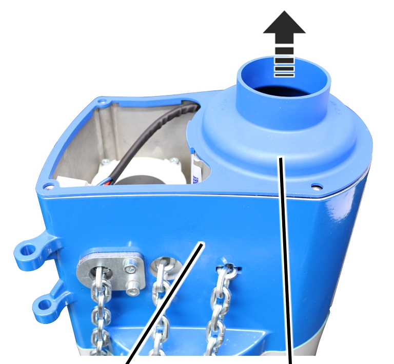
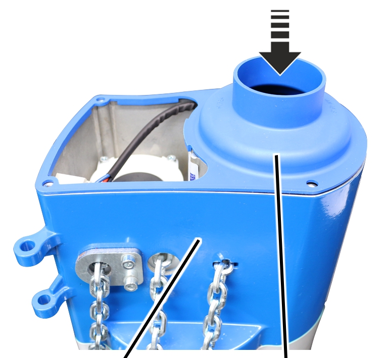
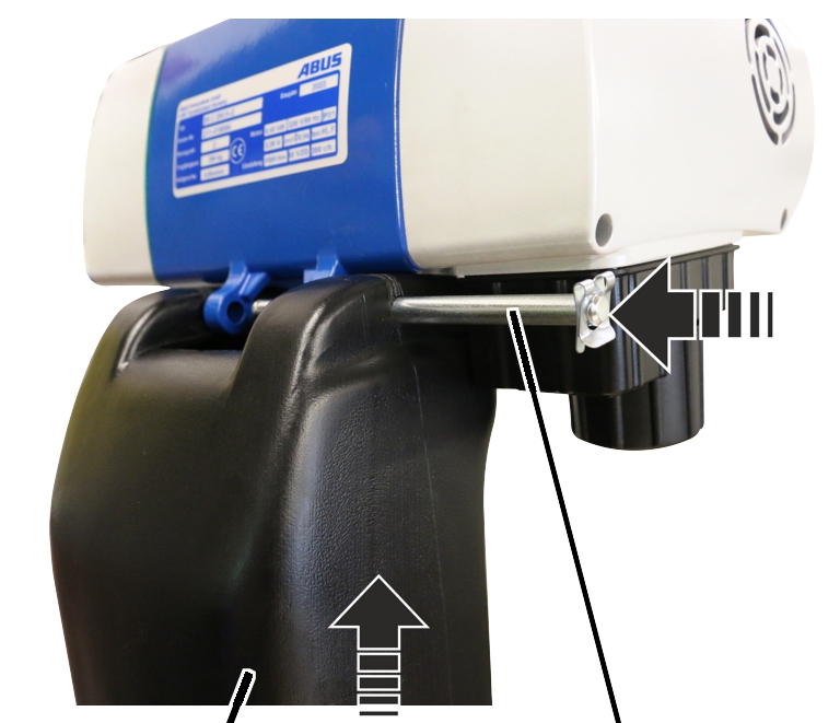
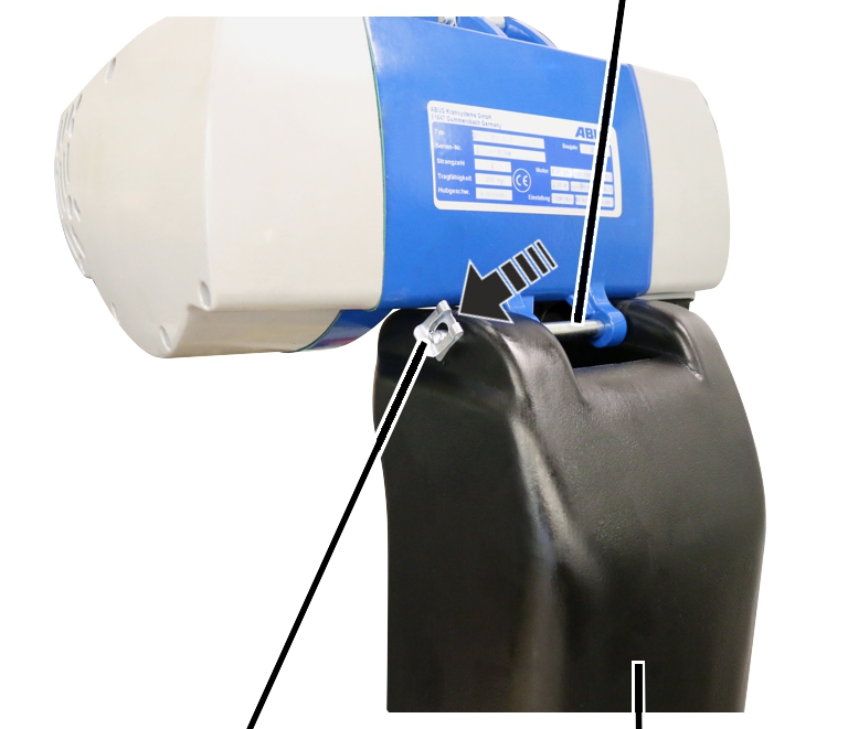
Chain box |
Bolt |
Detach the SL safety clip from
the bolt.
Hold the chain box firmly and
pull out the bolt.
Remove the chain box.
|
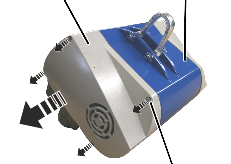
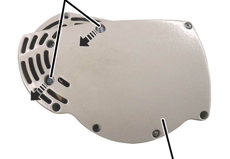
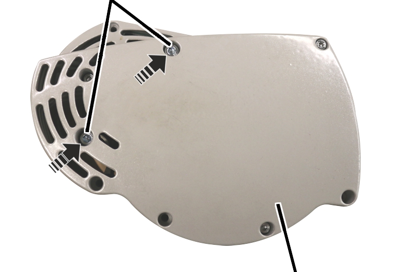
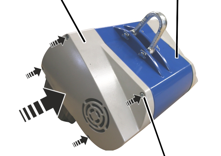
Motor cover |
Housing |
|
| |
|
|
Fillister-head screw |
 Unscrew the motor cover from the
housing.
Unscrew the motor cover from the
housing.
|
|
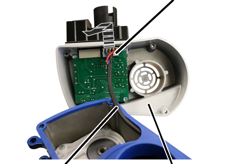
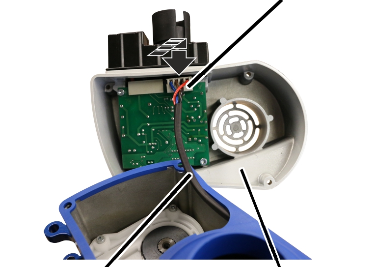
Connector |
|
| |
|
Motor connection cable |
Motor cover |
 Unplug the connector of the
motor connection cable from the circuit board.
Unplug the connector of the
motor connection cable from the circuit board.
|
| |
|
Housing |
Seal |
 Remove seal.
|
Fillister-head screw |
|
|
| |
|
|
Gearbox cover |
Turn housing over.
Unscrew the M5 fillister-head
screws (2x) from the gearbox cover and detach the motor.
|
Motor connection cable |
|
|
| |
|
|
Motor |
Pull the motor out of the
housing.
|
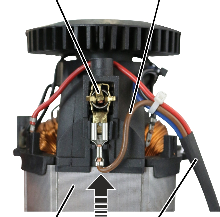
Carbon brush |
|
|
| |
|
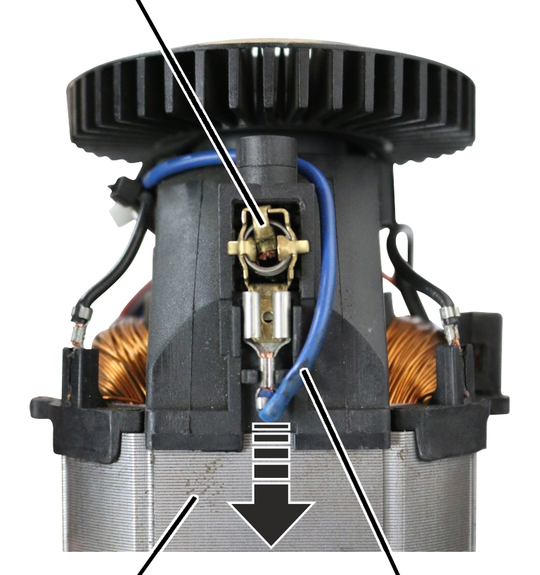
Motor |
Blue strand |
Pull the blue strand of the
motor connection cable from the carbon brush.
|
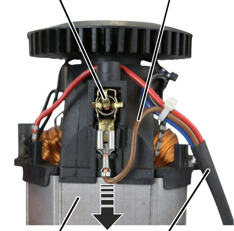
Carbon brush |
Brown strand |
|
| |
|
Motor |
Motor connection cable |
Pull the brown strand of the
motor connection cable from the carbon brush.
|
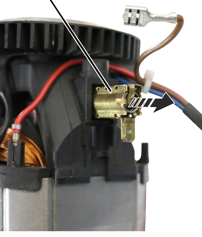
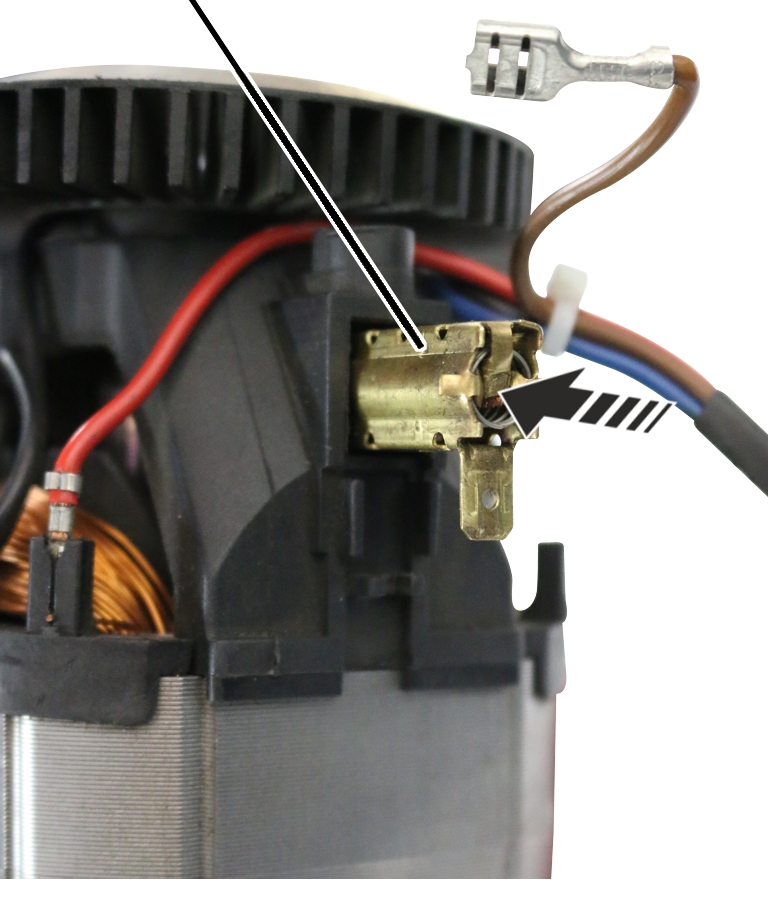
Carbon brush |
|
|
| |
Pull the carbon brushes (2x) out
of the motor.
|
Carbon brush |
|
|
| |
Push new carbon brushes (2x)
into the motor.
|
Carbon brush |
Brown strand |
|
| |
|
Motor |
Motor connection cable |
Push the brown strand of the
motor connection cable onto the carbon brush.
|
Carbon brush |
|
|
| |
|
Motor |
Blue strand |
Push the blue strand of the
motor connection cable onto the carbon brush.
|
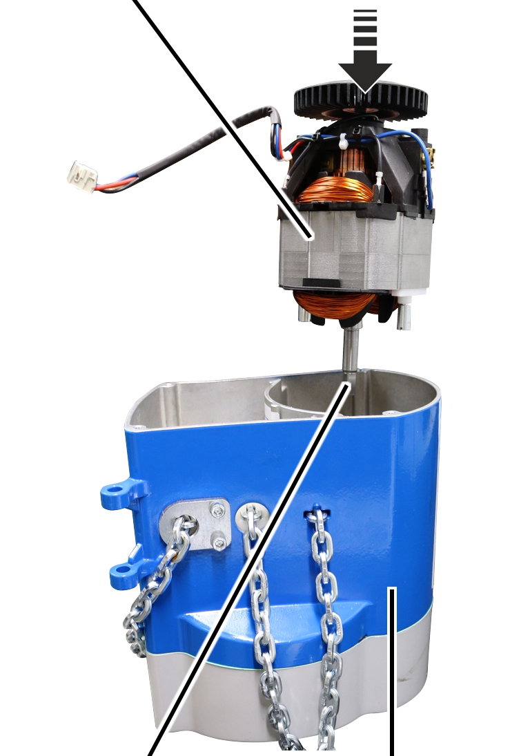
Motor |
|
|
| |
|
Motor shaft |
Housing |
Insert motor in the housing.
When doing this, ensure that the motor shaft fits precisely in the hole of the plastic pinion of the gear unit.
|
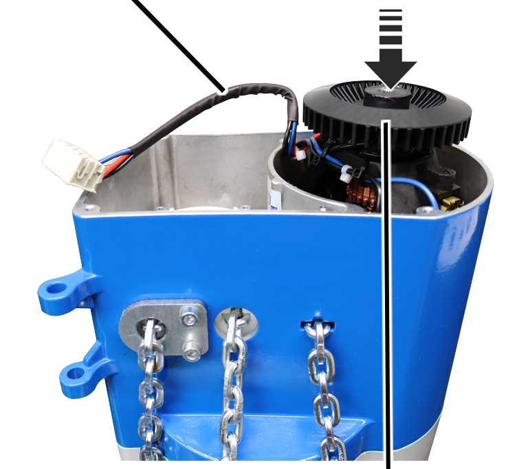
Motor connection cable |
|
|
| |
|
|
Fan blades on the motor shaft |
Press motor into the plastic
pinion as far as it will go.
By moving the fan blades slightly back and forth, the square-end on the motor shaft can be brought together with the square-end in the plastic pinion.
|
Motor |
|
|
| |
● The motor shaft sits precisely in the plastic pinion of the gear unit.
|
Fillister-head screw M5 |
|
|
| |
|
|
Gear unit |
Turn housing with motor
over.
Screw the M5 fillister-head
screws (2x) into the gear unit and screw the motor tight. 6 Nm.
|
| |
|
Housing |
Seal |
Press seal flush onto the
housing.
|
|
Connector |
|
| |
|
Motor connection cable |
Motor cover |
Plug the connector of the motor
connection cable into the circuit board in the motor cover.
|
Motor cover |
Housing |
|
| |
|
|
Fillister-head screw |
Hold the motor cover on the
housing.
Screw the motor cover tight with
M4x55 fillister-head screws (3x) and a M4x20 fillister-head screw (1x).
5 Nm.
|
| |
|
Chain box |
Bolt |
Turn the chain box so that it
appears as shown in the figure.
Place the chain in the chain
box.
Use the bolt to install the
chain box on the chain hoist.
|
|
Bolt |
|
| |
|
SL safety clip |
Chain box |
Push the SL safety clip onto the
bolt.
|
Connection cable |
Socket |
|
| |
|
|
Control cable with bayonet connector and bayonet nut |
Insert the connector of the
connection cable into the chain hoist.
Slide on the bayonet nuts of the
pendant control.
Insert the bayonet connector in
the chain hoist.
Tighten the bayonet nuts of the
pendant control.