If there is a defect, the hoist motor can be disassembled
from the gear unit and replaced individually. Because of the modular
construction, the gear unit does not need to be disassembled.
The images show the replacement on a GM 6000 hoist drive. The
replacement of a hoist motor in a different size does not essentially
differ.
|

|
Danger from falling bottom block!
If the hoist drive, the hoist motor or the brake
are removed, the cable drum of the wire rope hoist will no longer be
supported. This can cause the wire rope to unwind in an uncontrolled
manner and fall down with the bottom block.
Secure the bottom block on the wire rope
hoist! |
Selecting the
installation option
Preferred option: Hoist motor vertically disassembled toward the
top:
The safest option is disassembly of the hoist motor
vertically toward the top from a hoist drive that is lying down. For this, the
hoist drive must first be disassembled from the wire rope hoist. This option
should preferably be selected when possible.
 Disassemble the hoist
drive. See Installing
the hoist drive.
Disassemble the hoist
drive. See Installing
the hoist drive.
Turn the hoist drive and
lay it on the gear unit.
Alternatively: Support the hoist motor horizontally from
below:
The hoist motor can be replaced horizontally if the hoist
drive is mounted on the wire rope hoist. Depending on the accessibility on the
wire rope hoist, the hoist motor may need to be supported from below, e.g. with
a suitable forklift.
During replacement, the hoist motor must be secured so that
the weight can be safely held.
Alternatively: Secure the hoist motor horizontally from above:
Depending on the installation situation, the hoist motor can
also be replaced horizontally while being held from above. For this, a movable
slinging point is attached in the housing of the hoist motor. Since the cable
drum housing is located directly above the hoist motor, the slinging point is
usually not easily accessible.
Disassembling
the hoist motor
The images show the replacement on a vertically positioned
hoist drive.
Unscrew the rib screws
(3x) of the fan cover.
Take off the fan
cover.
|
|
Danger from falling load when slinging directly
on the motor shaft!
The slinging point on the motor shaft is not
intended for slinging the entire hoist drive. If the entire hoist drive is
slung there, the slinging point can break and the hoist drive can fall
down.
Use the slinging point on the motor shaft only for
the individual hoist motor. |
|
Eyebolt
with lifting tackle |
Hoist
motor |
|
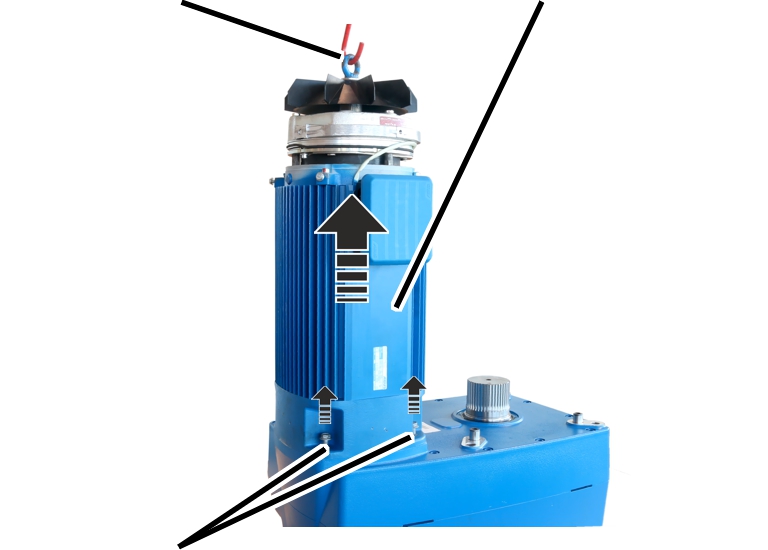
|
|
Rib
screws |
|
Only with fan blades on
the motor shaft: Screw a suitable eyebolt into the motor shaft and sling
suitable lifting tackle in the eyebolt.
Only with auxiliary fans:
Disassemble auxiliary fan and screw an eyebolt into the motor shaft.
If no eyebolt can be screwed into the motor shaft: Use suitable
lifting tackle with which the hoist motor can be lifted vertically.
Release the rib screws
(4x).
Lift the hoist motor.
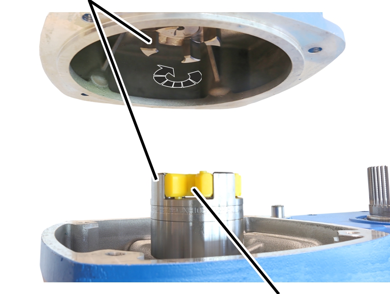
● The
coupling halves between hoist motor and hoisting gear slide apart.
● The hoist
motor is disassembled.
Installing the
hoist motor
The images show the replacement on a vertically positioned
hoist drive.
|
Coupling
halves |
|
|
|
|
|
Coupling
star |
Bring the hoist motor over
the hoisting gear.
Turn the hoist motor so
that the connector housing faces the exterior of the subsequently mounted hoist
drive.
Insert the coupling star
on the coupling half on the hoisting gear.
Turn the coupling halves
on the hoisting gear so that the coupling halves from the hoist motor and from
the hoisting gear lie exactly over one another and mesh into each other during
the assembly.
In the case of a removed hoist drive, the coupling half on the
gear unit can be turned.
Insert the hoist motor on
the hoisting gear.
● The
coupling halves slide into each other in the coupling star.
Tighten the rib screws
(4x) on the hoist motor.
|
Size |
Size and
length |
Tightening
torque |
|
GM800.4 |
M8x25 |
35 Nm |
|
GM1000.6 |
M8x25 |
35 Nm |
|
GM2000.3 |
M8x25 |
35 Nm |
|
GM3000.4 |
M10x30 |
50 Nm |
|
GM5000.3 |
M10x30 |
50 Nm |
|
GM6000.4 |
M10x30 |
50 Nm |
|
GM7000.1 |
M10x30 |
50 Nm |