Compare the operating voltage
and frequency range on the type plate with the mains voltage and frequency of
the local grid.
Compare the operating voltage
and frequency range on the type plate with the mains voltage and frequency of
the local grid.
The hoist drive is only intended for connection to an ABULiner frequency converter or to ABUControl.
Compare the operating voltage
and frequency range on the type plate with the mains voltage and frequency of
the local grid.
|
|
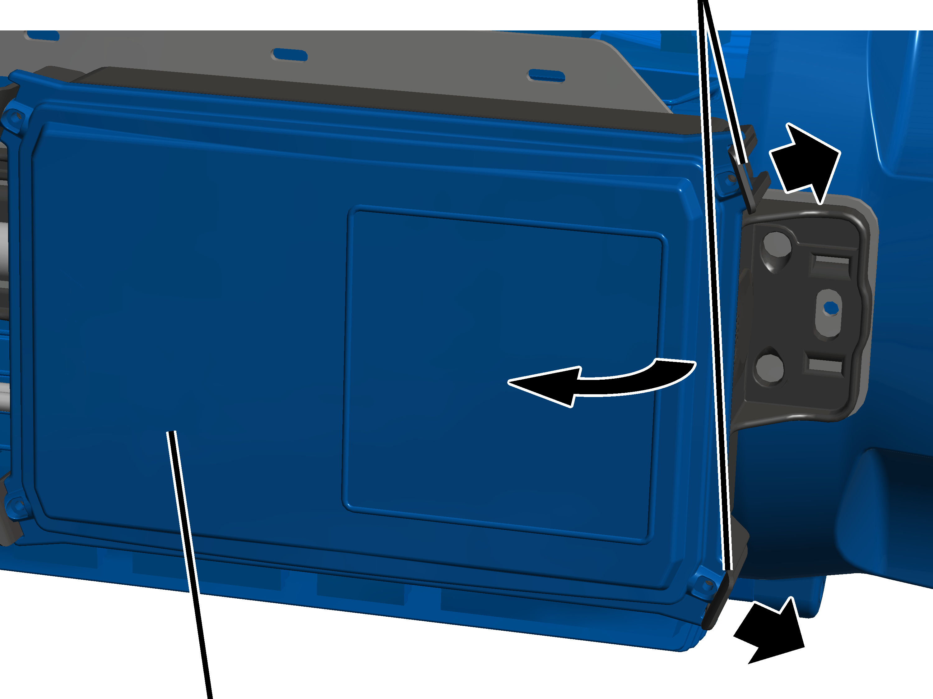
Clip fasteners |
|
| |
|
Cover |
|
Lightly push the two clip
fasteners one one side slightly outwards.
At the same time, pull the cover
on this side away from the housing.
|
| |
|
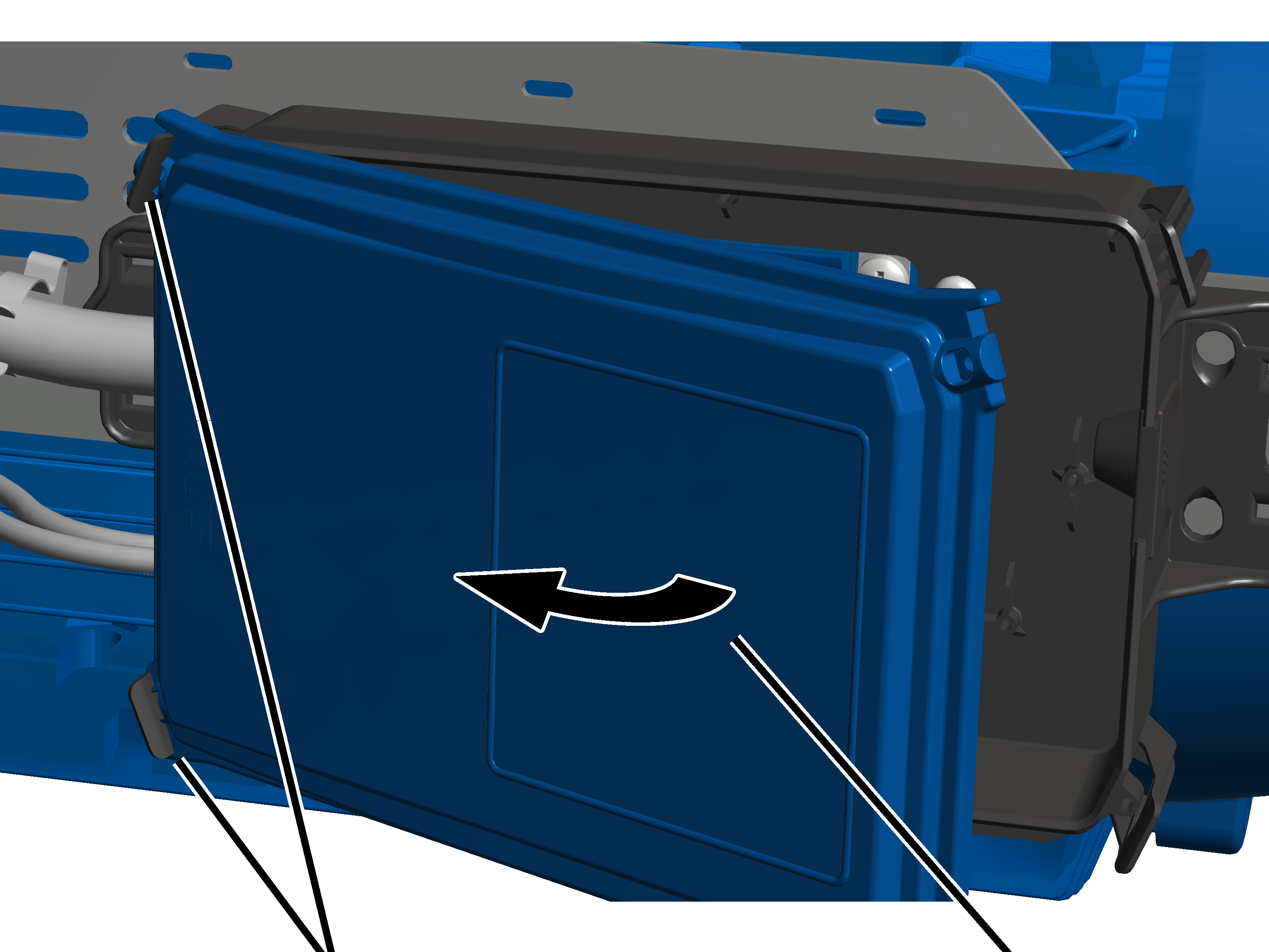
Clip fasteners |
Cover |
Tilt the cover to the side until
it is almost perpendicular to the housing.
● The lid automatically releases from the clip fasteners on the other side when tilted.
Put the cover aside.
|
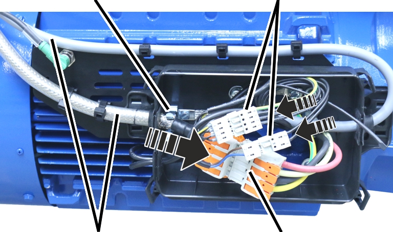
Screening clamp connection |
Plug-in connections for the brake and auxiliary fan |
|
| |
|
Connection cables for the hoist drive, brake, and auxiliary fan |
Plug-in
connection for |
Insert the connection cables for
the hoist drive into the pin multipoint connectors on the hoist drive.
Depending on size and options of the hoist drive, the plug-in connections are of different sizes.
Insert the connection cables for
the brake and auxiliary fan into the pin multipoint connectors on the hoist
drive.
Lay the plug-in connections and
connection cable in the connector housing.
Push the front end of the hoist
drive connection cable (where the sheathing around the shield has been removed)
into the screening clamp connection.
|
Connector for the incremental rotary encoder |
|
|
| |
|
Cable ties |
Cable bushing |
Push the connection cable with
the cable bushing into the housing.
Insert the rubber lips of the cable bushing so that they lay flat against the housing both inside and outside.
Fasten the connection cables
with cable clips.
Plug the connector in for the
incremental rotary encoder.
|
| |
|
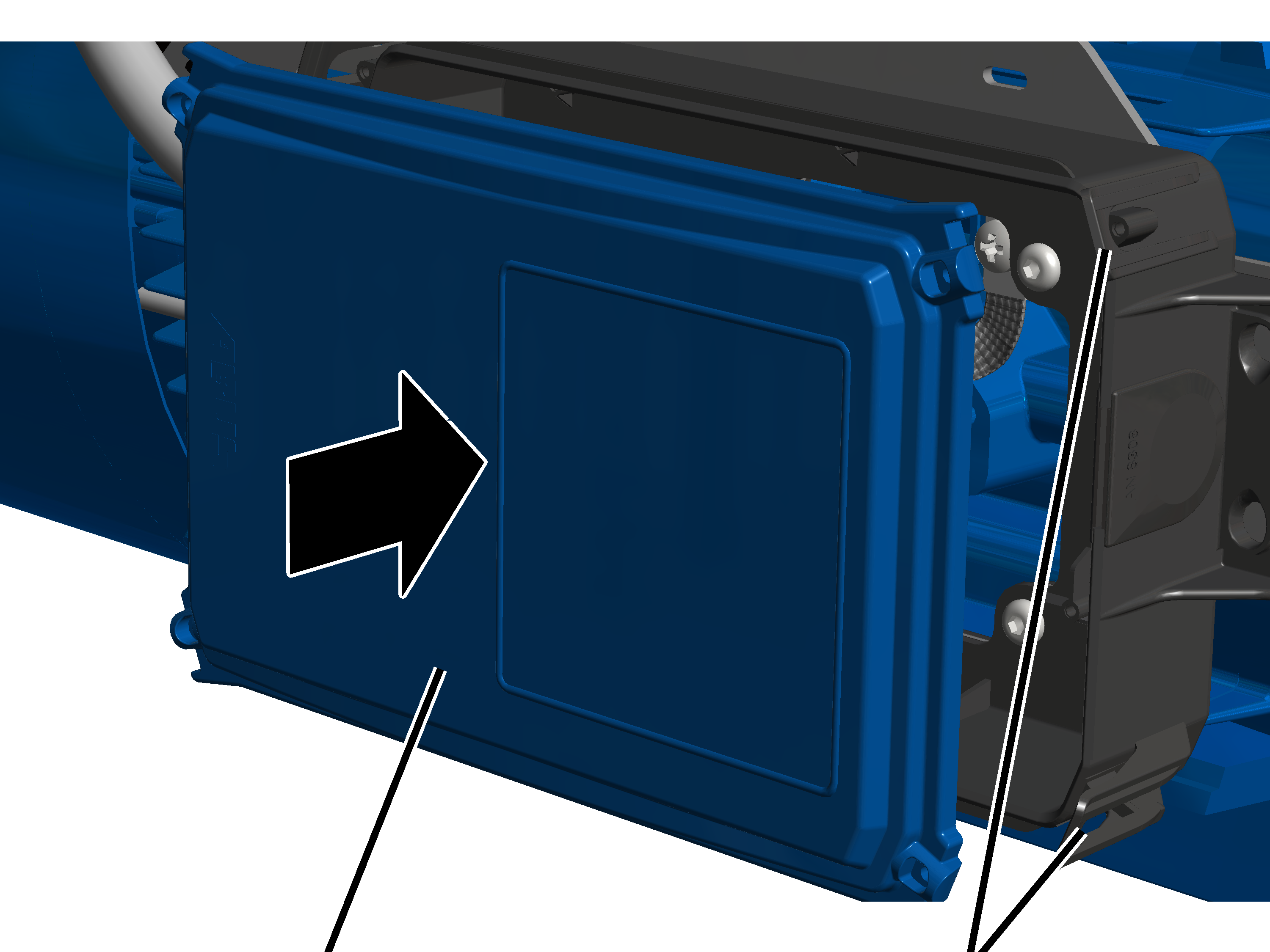
Cover |
Clip fasteners |
Place all four corners of the
cover onto the housing.
Press the cover into all four
locking clips at the same time until they snap into place.
|
Pin multipoint connector |
Terminal |
Assignment |
|
832 |
1 |
Winding of the hoist motor (U) |
|
|
2 |
Winding of the hoist motor (V) |
|
|
3 |
Winding of the hoist motor (W) |
|
|
4 |
Protective conductor |
|
723 |
1 |
Brake |
|
|
2 |
Brake |
|
721 |
1 |
Auxiliary fan (U) |
|
|
2 |
Auxiliary fan (V) |
|
|
3 |
Auxiliary fan (W) |
|
|
4 |
Protective conductor |
Observe the polarity and connect
the auxiliary fan to the terminals 721, 1 and 4.
The direction of rotation of the auxiliary fan is marked with an arrow on the fan cover. The direction of rotation is determined by the rotary field of the auxiliary fan. If the field of rotation is incorrect, the auxiliary fan will rotate in the wrong direction and the hoist motor will not be cooled sufficiently.
Connect the brake to the
terminals 723.1 and 2.
Connect the winding of the hoist
motor to the terminals 823.1 1 and 4.