Special wiring diagrams can be obtained from ABUS Service.
See page 89.
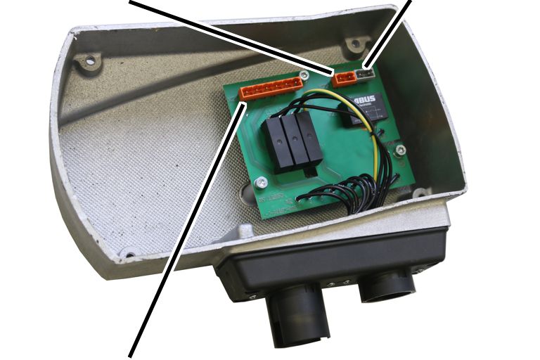
Only for GM2, GM4 and GM6
with direct control
Control in the
motor cover
|
Pin plug
for star points |
Pin plug
for brake |
|
|
|
Pin plug
for hoist motor |
|
─ The
electricity for the hoist motor is controlled directly through the buttons of
the pendant control and is switched from there.
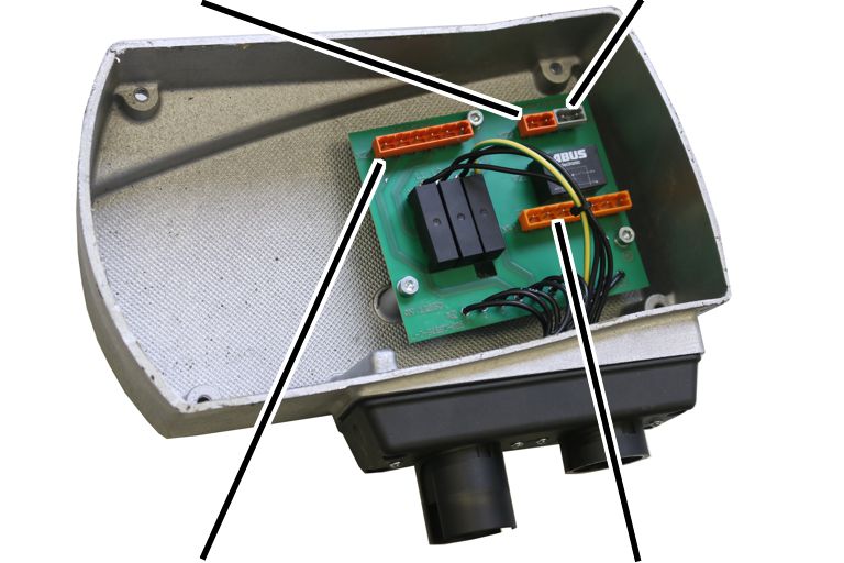
Only for GM2, GM4 and GM6
with electric hoist trolley
Control in the
motor cover
|
Pin plug
for star points |
Pin plug
for brake |
|
|
|
Pin plug
for hoist motor |
Pin plug
for trolley travel motor |
─ The
electricity for the hoist motor and the trolley travel motor is controlled
directly through the buttons of the pendant control and is switched from
there.
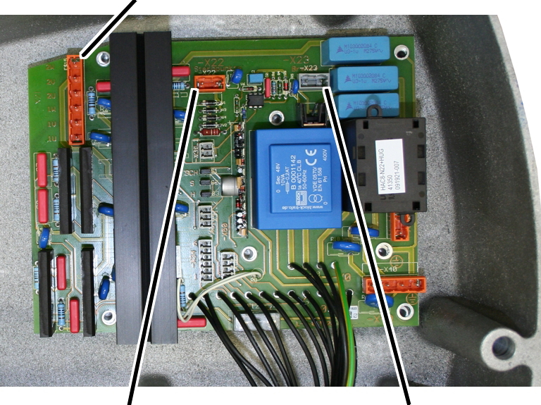
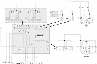
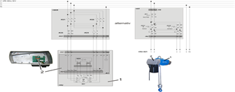
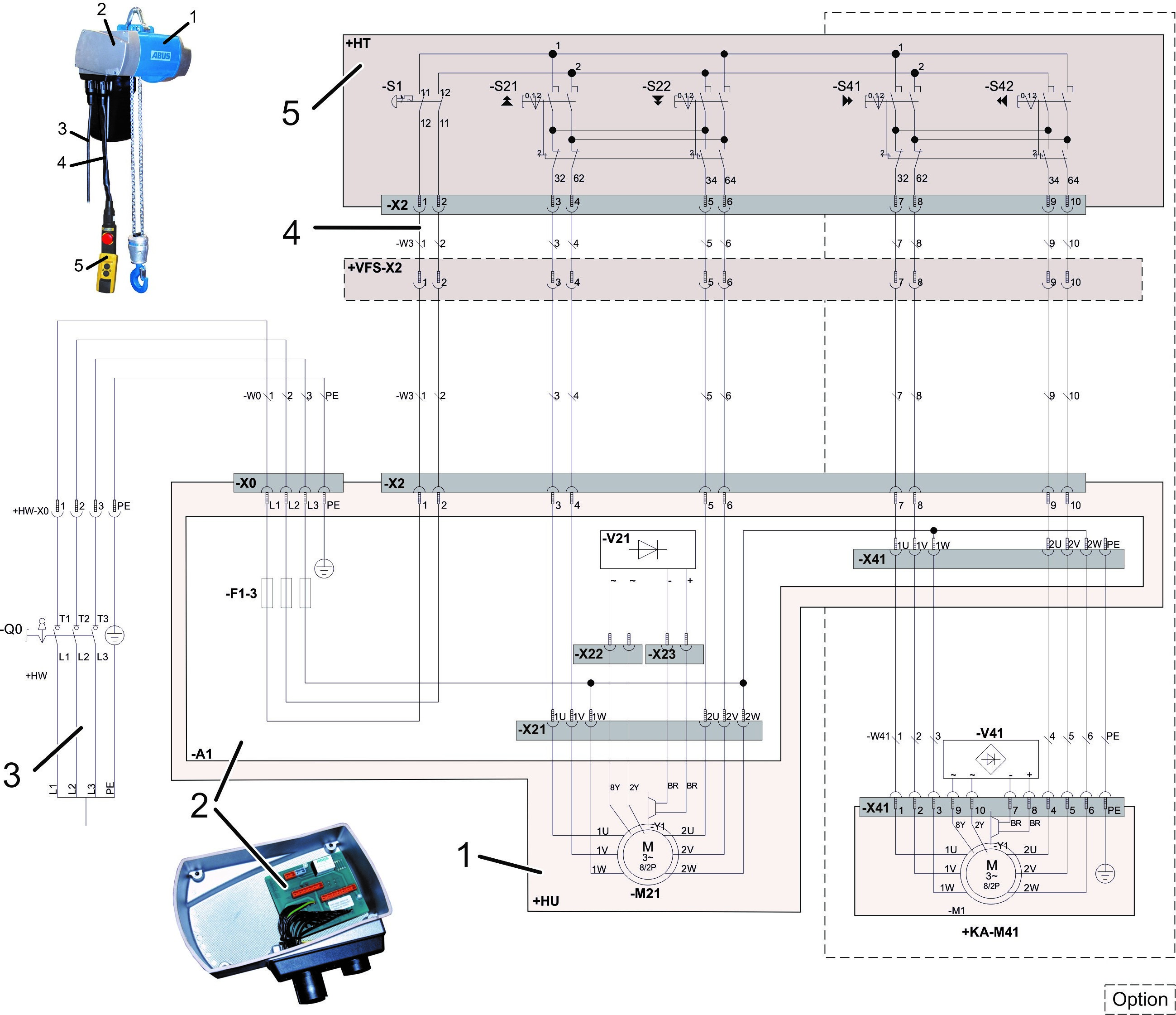
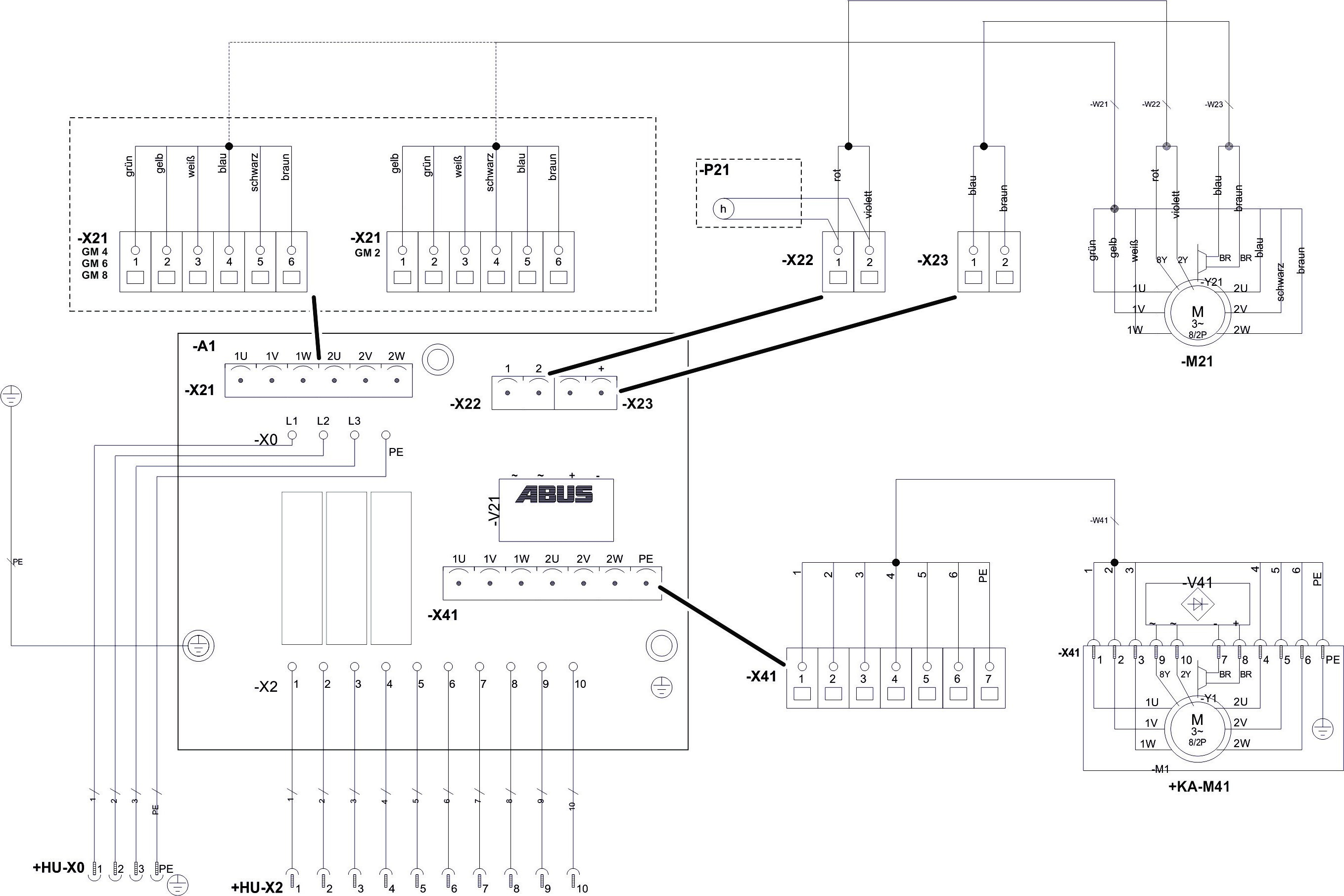
Only for GM2 and GM4 with
electronic control
Control in the
motor cover
|
Pin plug
for star points |
Pin plug
for hoist motor |
Semiconductor relay PCB |
|
|
|
Supply
PCB |
Pin plug
for brake |
|
|
|
|
─ The
electricity for the hoist motor is controlled through a semiconductor relay
which is switched from a 48 V control voltage.
─ The
control voltage can be switched using a pendant control or radio remote
control.
─ The
control consists of a supply PCB and a semiconductor relay PCB attached above
it.
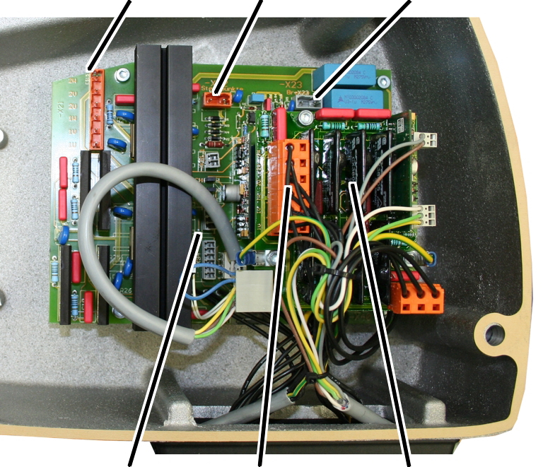
Only for GM2 and GM4 with
electronic control and electric hoist trolley
Control in the
motor cover
|
Pin plug
for trolley travel motor |
Semiconductor relay PCB |
Pin plug
for hoist motor |
|
|
|
Pin plug
for star points |
Semiconductor relay PCB |
Pin plug
for brake |
|
|
|
|
─ The
electricity for the hoist motor is controlled through a semiconductor relay
which is switched from a 48 V control voltage.
─ The
control voltage can be switched using a pendant control or radio remote
control.
─ The
control consists of a supply PCB and two semiconductor relay PCBs attached above
it. One of them controls the hoist motor, the other controls the trolley travel
motor.
─ In the
GM2, the installation of this electronic control is only possible through an
additional housing.
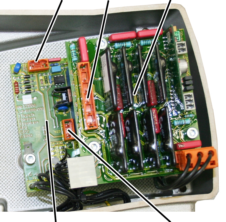
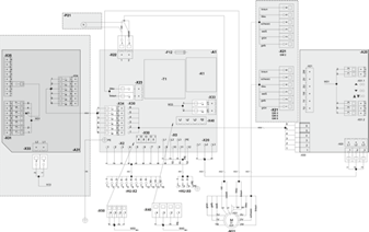
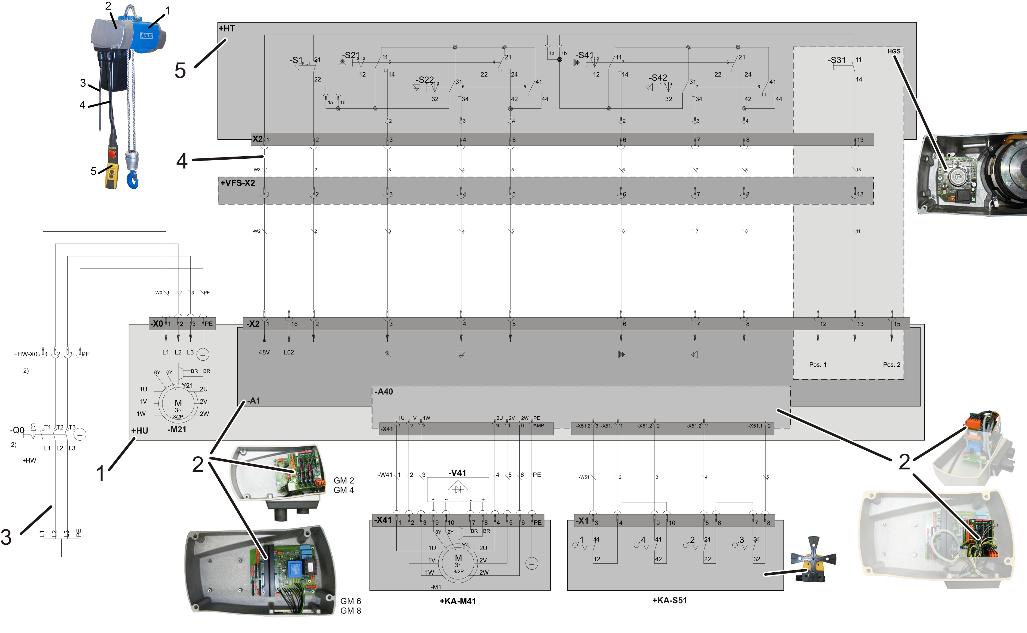
Only for GM6 and GM8 with
electronic control
Control in the
motor cover
|
Pin plug
for hoist motor |
|
|
|
|
Pin plug
for star points |
Pin plug
for brake |
─ The
electricity for the hoist motor is controlled through a semiconductor relay
which is switched from a 48 V control voltage.
─ The
control voltage can be switched using a pendant control or radio remote
control.
─ The
control consists of a supply PCB on which there are also semiconductor
relays.
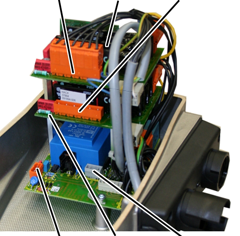
Only for GM6 and GM8 with
electronic control and electric hoist trolley
Control in the
motor cover
|
Pin plug
for hoist motor |
Pin plug
for star points |
Pin plug
for brake |
|
|
|
Supply
PCB |
Pin plug
for trolley travel motor |
Semiconductor relay PCB |
─ The
electricity for the hoist motor is controlled through a semiconductor relay
which is switched from a 48 V control voltage.
─ The
control voltage can be switched using a pendant control or radio remote
control.
─ The
control consists of a supply PCB on which there are also semiconductor relays
for the control of the hoist motor and a semiconductor relay PCB attached above
for the control of the trolley travel motor.
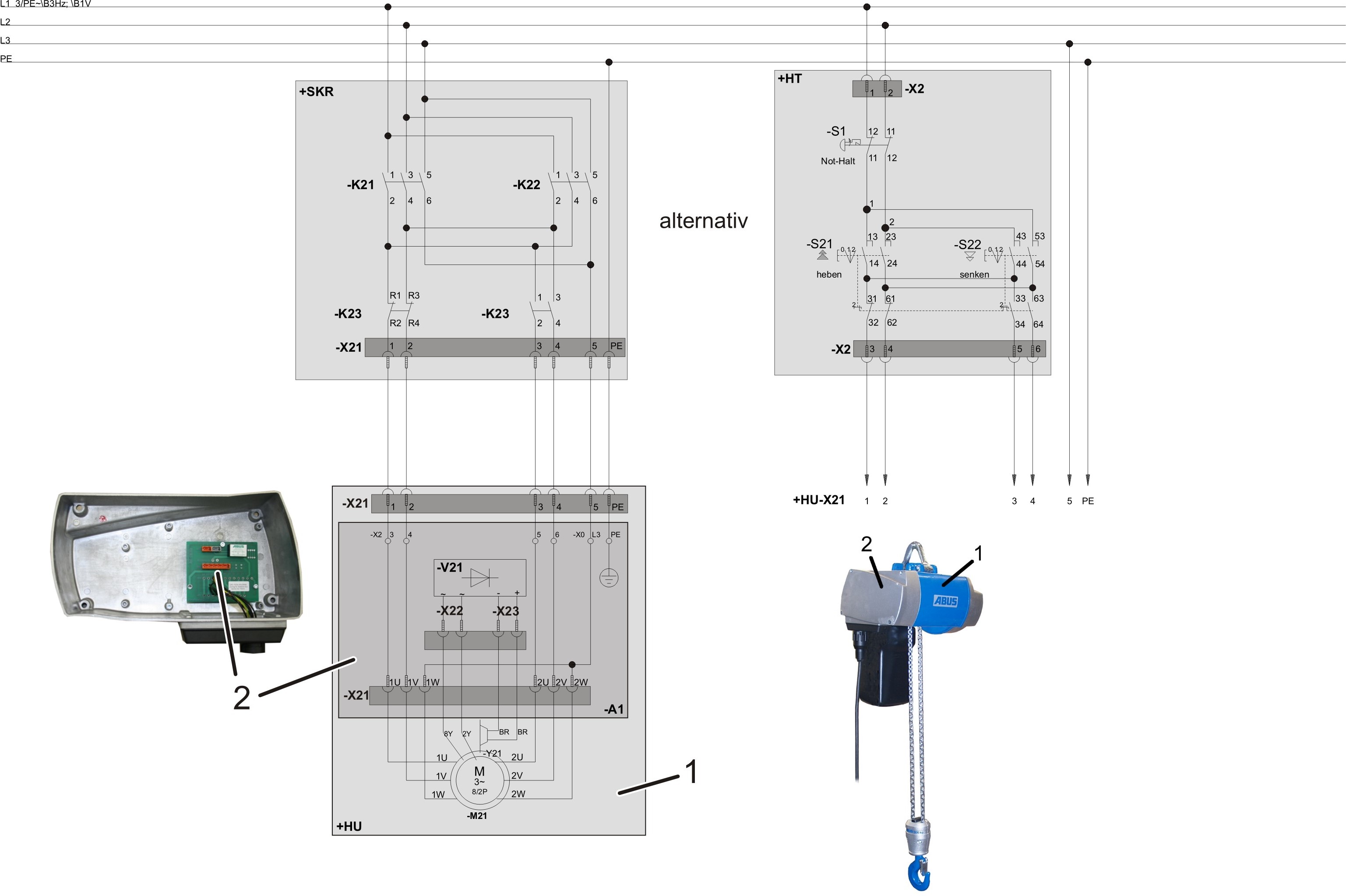
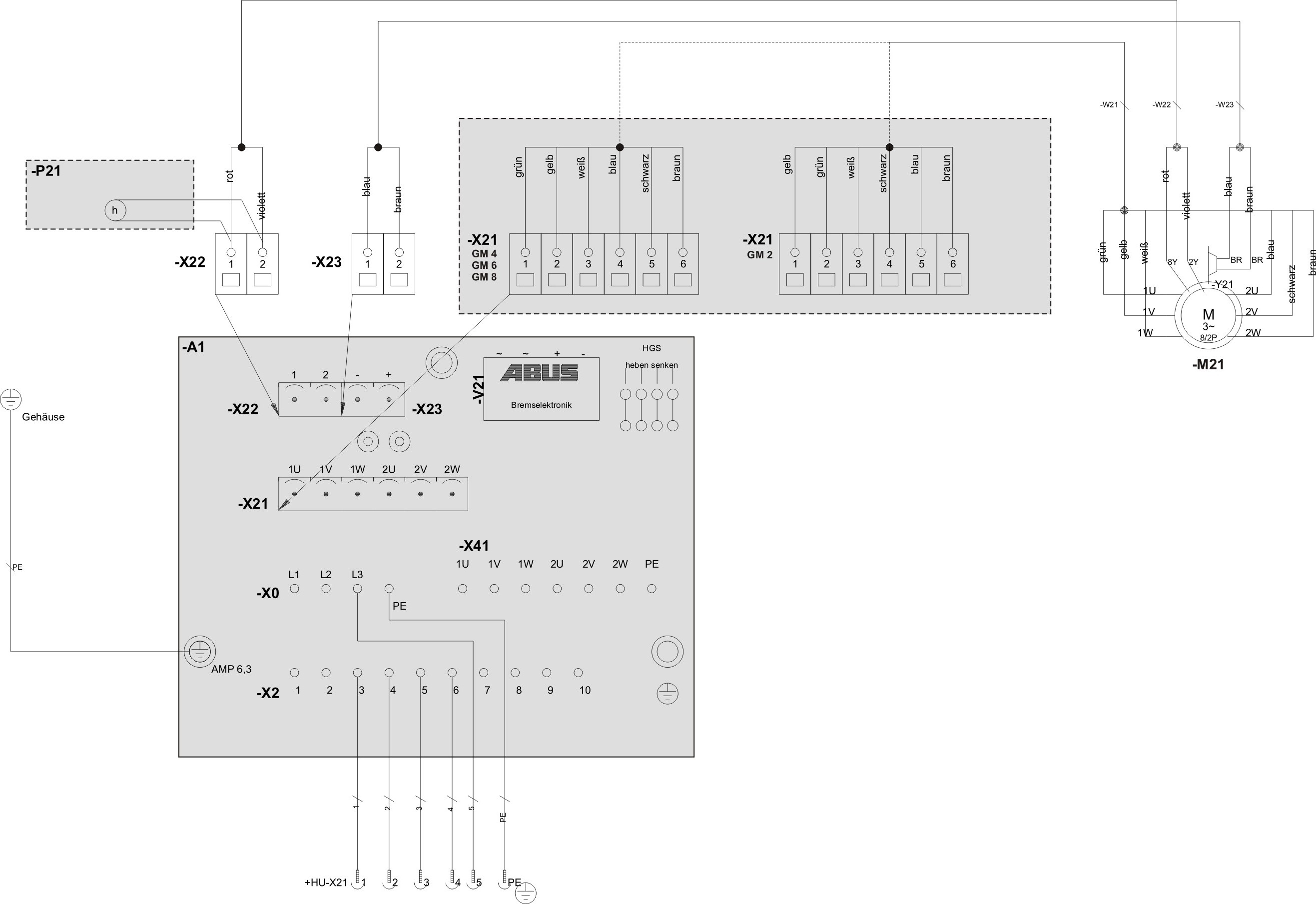
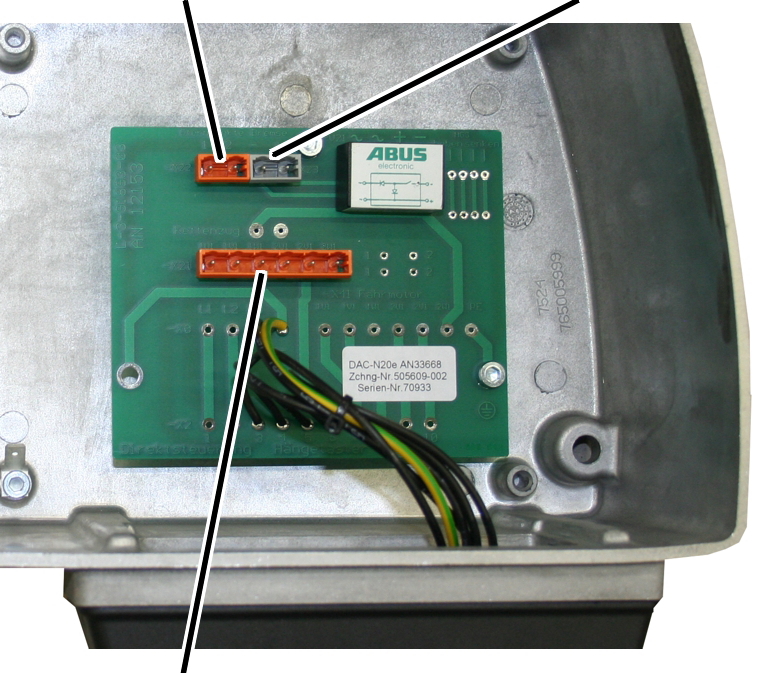
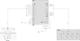
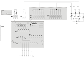
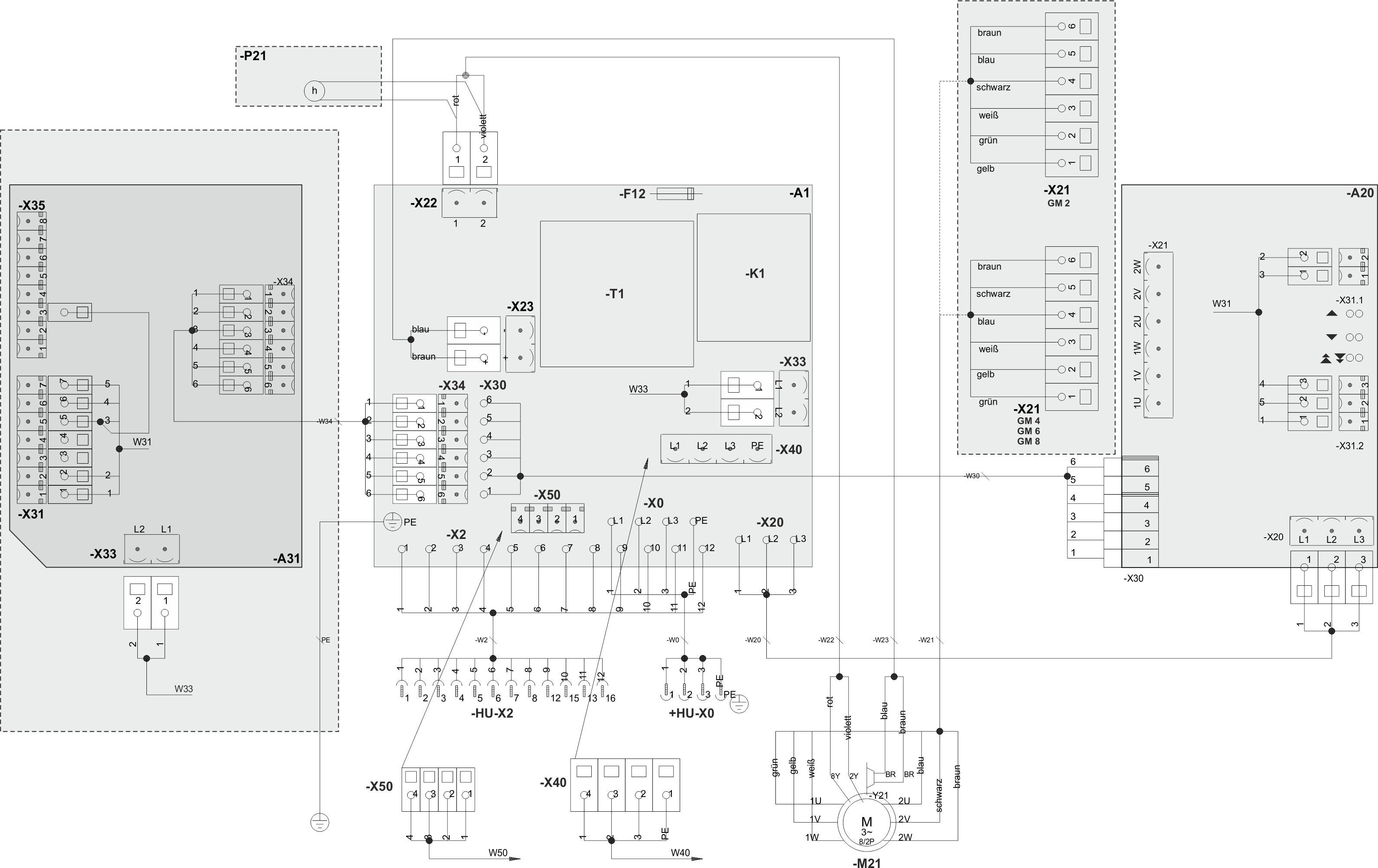
Only for external
control
Control in the
motor cover
|
Pin plug
for star points |
Pin plug
for brake |
|
|
|
Pin plug
for hoist motor |
|
─ The
electricity for the hoist motor is controlled in an external control (e.g.
inside a panel).
─ The
circuit board of the external control conducts the electricity to the hoist
motor and handles the control of the brake.
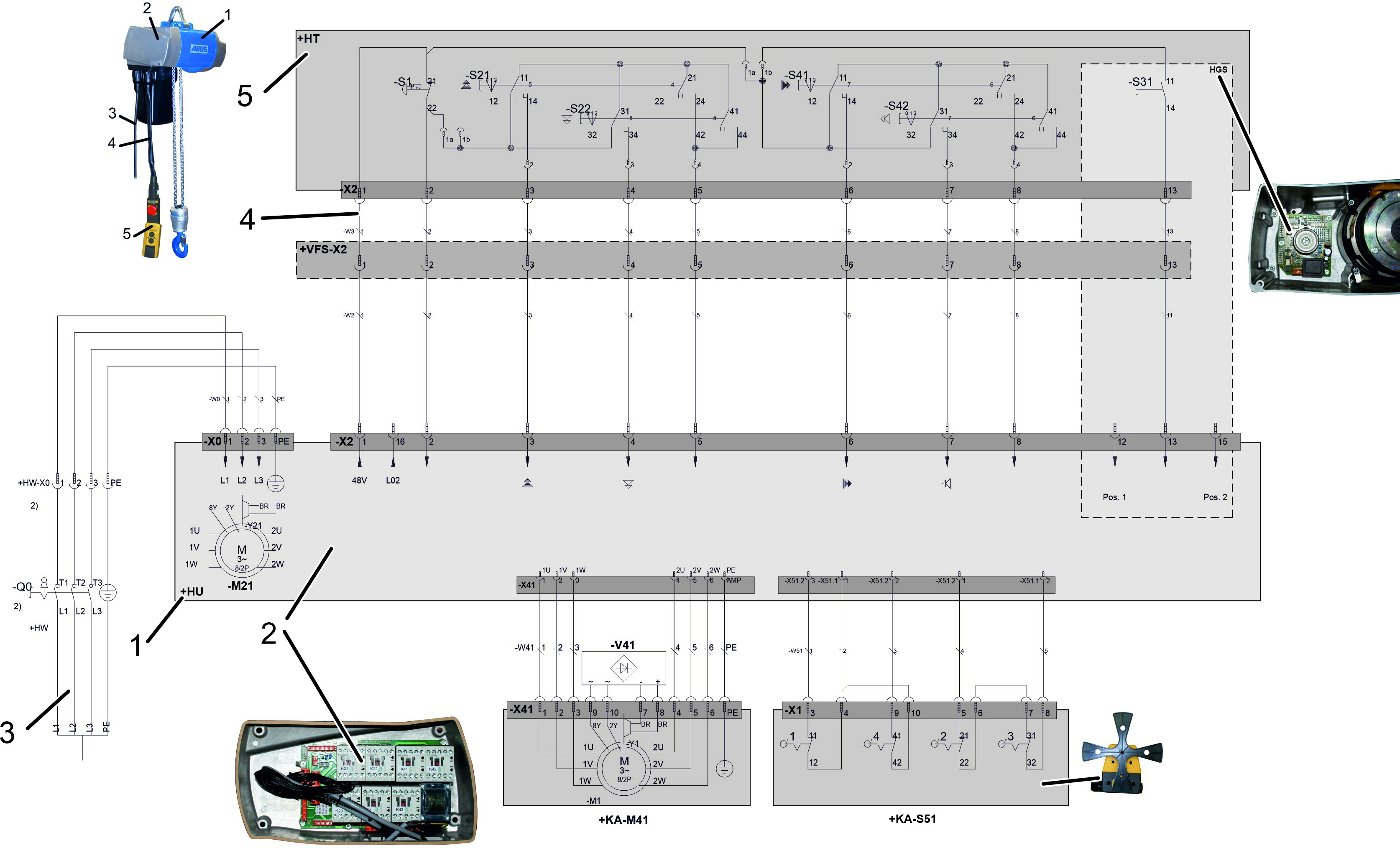
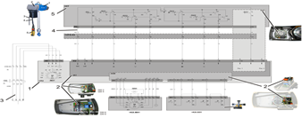
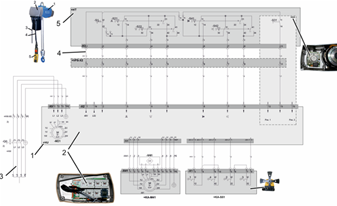
Only for ABULiner
The electricity of the hoist motor is controlled by a
frequency converter in a variable frequency. This enables continuous control of
the speed of the chain hoist. The frequency converter is mounted on the chain
hoist in an additional housing. With additional frequency converters, the
trolley and crane speeds can also be continuously controlled. Wiring diagrams
for this can be obtained from ABUS Service. See page 89.
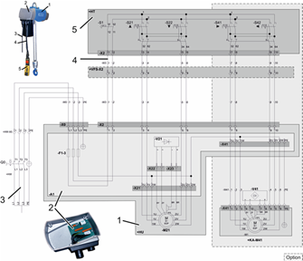
|
Abbreviation |
Designation |
|
+HT |
Pendant control |
|
-S1 |
Emergency stop button |
|
-S21 |
Lift button |
|
-S22 |
Lower button |
|
-S41 |
Trolley travel toward right button |
|
-S42 |
Trolley travel toward left button |
|
-S31 |
Teach-in hoist limit switch |
|
+VFS-X2 |
Mobile control |
|
+KA-M41 |
Trolley travel motor |
|
-M21 |
Hoist motor |
|
+HU |
Chain hoist |
|
-V21 |
Electronics for brake of hoist |
|
-V41 |
Electronics for brake of hoist trolley |
|
-A1 |
Supply PCB, direct control PCB or external control
PCB |
|
+HW |
Power line |
|
+KA-S51 |
Trolley travel limit switch |
|
+KA-S51.1 |
Right limit stop |
|
+KA-S51.4 |
Left limit stop |
|
+KA-S51.2 |
Braking function, right |
|
+KA-S51.3 |
Braking function, left |
|
-A40 |
Semiconductor relay PCB, trolley travel
motor |
|
HGS |
Hoist limit switch |
|
-P21 |
Operating hours counter |
|
-X0 |
Plug-in connection for connection cable |
|
-X2 |
Plug-in connection for pendant control |
|
-X41 |
Plug-in connection for trolley travel
motor |
|
-X21 |
Plug-in connection for hoist motor |
|
-X22 |
Plug-in connection for star points of hoist
motor |
|
-X23 |
Plug-in connection for brake of hoist
motor |
|
-A31 |
Hoist limit switch PCB |
|
+SKR |
Crane panel |
|
-A20 |
Semiconductor relay PCB |
|
-X31.1 |
For electronic hoist limit switch: detach
jumper |
|
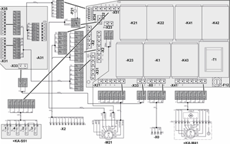
-K1 |
Main contactor |
|
-T1 |
Control transformer |
|
- F1-3 |
Fuses |
Direct control –
wiring diagram
|
|
|
|
|
|
Click image for
full size |
Direct control –
wiring diagram
|
|
|
|
|
|
Click image for
full size |
Electronic
control – wiring diagram
|
|
|
|
|
|
Click image for
full size |
Electronic
control – wiring diagram
|
|
|
|
|
|
Click image for
full size |
Electronic
control – wiring diagram
|
|
|
|
|
|
Click image for
full size |
External control
– wiring diagram
|
|
|
|
|
|
Click image for
full size |
External control
– wiring diagram
|
|
|
|
|
|
Click image for
full size |
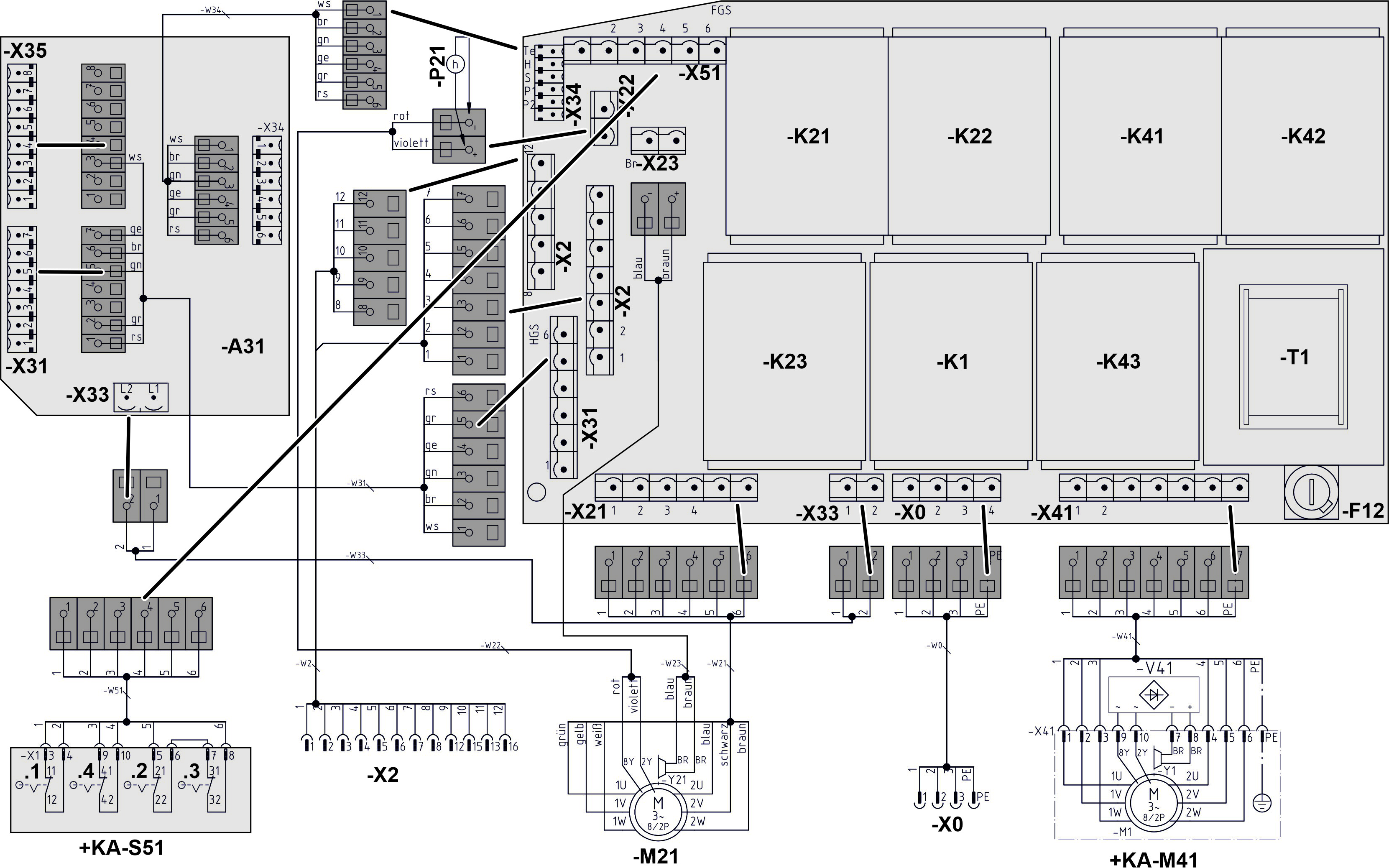
Contactor
control - wiring diagram
|
|
|
|
|
|
Click image for
full size |
Contactor
control - wiring diagram
|
|
|
|
|
|
Click image for
full size |
.jpg)