|
|
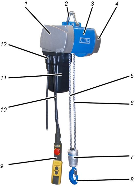
─ 1: Motor cover
─ 2: Suspension bracket
─ 3: Housing with hoist motor
─ 4: Gear unit
─ 5: Chain, first fall
─ 6: Chain, second fall (version)
─ 7: Bottom block
─ 8: Load hook
─ 9: Pendant control
─ 10: Control cable
─ 11. Chain box
─ 12: Connection cable with bayonet coupling
The chain hoist:
─ The chain hoist has a slow lifting speed and a fast lifting speed.
─ The chain hoist is controlled using the “ABUCommander” pendant control. Depending on the version, the pendant control hangs directly on the chain hoist or on a mobile control (version).
Alternatively, the chain hoist can be equipped with an “ABURemote AC” radio remote control. The receiver is thereby directly mounted on the chain hoist.
─ Single-fall chain hoist: The chain hoist has a rotating hook assembly with a fixed load hook. The load hook can thus be guided by the hook assembly.
─ The chain hoist has a chain.
─ The chain hoist is equipped with a folding, removable suspension bracket for easier installation. A hinged suspension hook can be used as an option.
─ The chain hoist is equipped with an adjustable friction clutch. This is factory set for 1.3 to 1.4 times the maximum load capacity. It is used as an emergency stop device and to protect against occasional mechanical overload. For chain hoists with a maximum load capacity over 1000 kg, the friction clutch fulfils the function of overload protection. It conforms to the requirements for direct-acting overload protection according to DIN EN 14492-2.
─ The chain hoist is of a modular construction. Gear unit and housing can thus be easily removed and exchanged.
─ The chain hoist has a removable chain guide and chain sprocket. This enables quick exchange of wearing parts.
─ The chain hoist can be equipped with an ABULiner for continuously variable control of the lifting speed (optional).
─ Only for chain hoist with electronic control: The chain hoist can be equipped with an operating hours counter (optional).
For the chain hoists GM2 and GM4:
─ The suspension bracket can be rotated 90°.
For the chain hoists GM2, GM4 and GM6:
─ The chain hoist is equipped with direct control 400 V / 50 Hz as standard.
─ Only for direct control without electric trolley travel and for direct control with electric trolley travel: The chain hoist has three-pole protection with integrated fuses.
─ The chain hoist can be equipped with electronic control using maintenance-free semiconductor technology with 48 V control voltage (optional).
For chain hoist GM8:
─ The chain hoist is equipped with electronic control using maintenance-free semiconductor technology with 48 V control voltage.
For chain hoists with electronic control:
─ The chain hoist can be equipped with ABURemote AC radio remote control (optional),
For chain hoists with a mechanical hoist limit switch:
─ The chain hoist can be equipped with a mechanical hoist limit switch (optional).
─ An upper and a lower switching point can be set with the mechanical hoist limit switch. When the load hook reaches one of the switching points, the chain hoist brakes and halts.
─ The switching points of the mechanical hoist limit switch can be used in combination with a contactor control as a hoist limiter.
─ The switching points may be triggered during normal operation. If the microswitches of the hoist limit switch wear out due to regular use, the friction clutch of the chain hoist serves as an emergency end stop device.
For chain hoists with an electronic hoist limit switch:
─ The chain hoist can be equipped with an electronic hoist limit switch with teach-in function (optional).
─ An upper and a lower switching point can be set with the electronic hoist limit switch. When the load hook reaches one of the switching points, the chain hoist brakes and halts.
─ Optionally, an additional switching point can be located between the two switching points as an intermediate switching point. If this additional switching point is programmed, the chain hoist brakes as soon as the load hook approaches the intermediate switching point and halts there. The switching point can then be overrun by releasing the button for lifting/lowering and pressing it again (stop-and-go).
─ The switching points on the electronic hoist limit switch are programmed with a supplied teach-in module, which is plugged in instead of the pendant control.
Alternatively, a pendant control with an additional teach-in button is also available.
With ABURemote AC, the teach-in function can be operated remotely (optional).
Electrical connection
|
|
GM2 (all versions) | ||
|
Operating voltage |
220 –240 V |
380 –415 V |
460 –500 V |
|
Mains frequency |
50 Hz |
50 Hz |
50 Hz |
|
Duty cycle |
60 % |
60 % |
60 % |
|
Switching rate |
360 c/h |
360 c/h |
360 c/h |
|
Rated power |
0.09 kW |
0.09 kW |
0.09 kW |
|
Start-up current IA |
1.77 A |
1.02 A |
0.85 A |
|
cos phi A |
0.85 |
0.85 |
0.85 |
|
Rated current IN |
1.35 A |
0.80 A |
0.65 A |
|
cos phi N |
0.56 |
0.56 |
0.56 |
|
|
GM 2 (all versions) | ||
|
Operating voltage |
208 – 230 V |
360 – 400 V |
440 – 480 V |
|
Mains frequency |
60 Hz |
60 Hz |
60 Hz |
|
Duty cycle |
60 % |
60 % |
60 % |
|
Switching rate |
360 c/h |
360 c/h |
360 c/h |
|
Rated power |
0.11 kW |
0.11 kW |
0.11 kW |
|
Start-up current IA |
1.77 A |
1.02 A |
0.85 A |
|
cos phi A |
0.85 |
0.85 |
0.85 |
|
Rated current IN |
1.35 A |
0.80 A |
0.65 A |
|
cos phi N |
0.56 |
0.56 |
0.56 |
|
|
GM4 (all versions) | ||
|
Operating voltage |
220 – 240 V |
380 – 415 V |
460 – 500 V |
|
Mains frequency |
50 Hz |
50 Hz |
50 Hz |
|
Duty cycle |
60 % |
60 % |
60 % |
|
Switching rate |
360 c/h |
360 c/h |
360 c/h |
|
Rated power |
0.22 kW |
0.22 kW |
0.22 kW |
|
Start-up current IA |
4.80 A |
2.80 A |
2.30 A |
|
cos phi A |
0.85 |
0.85 |
0.85 |
|
Rated current IN |
2.60 A |
1.50 A |
1.30 A |
|
cos phi N |
0.70 |
0.70 |
0.70 |
|
|
GM 4 (all versions) | ||
|
Operating voltage |
208 – 230 V |
360 – 400 V |
440 – 480 V |
|
Mains frequency |
60 Hz |
60 Hz |
60 Hz |
|
Duty cycle |
60 % |
60 % |
60 % |
|
Switching rate |
360 c/h |
360 c/h |
360 c/h |
|
Rated power |
0.26 kW |
0.26 kW |
0.26 kW |
|
Start-up current IA |
4.80 A |
2.80 A |
2.30 A |
|
cos phi A |
0.85 |
0.85 |
0.85 |
|
Rated current IN |
2.60 A |
1.50 A |
1.30 A |
|
cos phi N |
0.70 |
0.70 |
0.70 |
|
|
GM6 (all versions) | ||
|
Operating voltage |
220 – 240 V |
380 – 415 V |
460 – 500 V |
|
Mains frequency |
50 Hz |
50 Hz |
50 Hz |
|
Duty cycle |
50 % |
50 % |
50 % |
|
Switching rate |
300 c/h |
300 c/h |
300 c/h |
|
Rated power |
0.40 kW |
0.40 kW |
0.40 kW |
|
Start-up current IA |
7.80 A |
4.50 A |
3.75 A |
|
cos phi A |
0.70 |
0.70 |
0.70 |
|
Rated current IN |
3.80 A |
2.20 A |
1.80 A |
|
cos phi N |
0.84 |
0.84 |
0.84 |
|
|
GM 6 (all versions) | ||
|
Operating voltage |
208 – 230 V |
360 – 400 V |
440 – 480 V |
|
Mains frequency |
60 Hz |
60 Hz |
60 Hz |
|
Duty cycle |
50 % |
50 % |
50 % |
|
Switching rate |
300 c/h |
300 c/h |
300 c/h |
|
Rated power |
0.50 kW |
0.50 kW |
0.50 kW |
|
Start-up current IA |
7.80 A |
4.50 A |
3.75 A |
|
cos phi A |
0.70 |
0.70 |
0.70 |
|
Rated current IN |
3.80 A |
2.20 A |
1.80 A |
|
cos phi N |
0.84 |
0.84 |
0.84 |
|
|
GM8 800.8-1 and 1600.4-2 | ||
|
Operating voltage |
220 – 240 V |
380 – 415 V |
460 – 500 V |
|
Mains frequency |
50 Hz |
50 Hz |
50 Hz |
|
Duty cycle |
50 % |
50 % |
50 % |
|
Switching rate |
300 c/h |
300 c/h |
300 c/h |
|
Rated power |
0.2 kW |
0.2 kW |
0.2 kW |
|
Start-up current IA |
6.00 A |
3.50 A |
2.90 A |
|
cos phi A |
0.75 |
0.75 |
0.75 |
|
Rated current IN |
4.30 A |
1.40 A |
2.10 A |
|
cos phi N |
0.56 |
0.56 |
0.56 |
|
|
GM 8 800.8-1, 1600.4-2 | ||
|
Operating voltage |
208 – 230 V |
360 – 400 V |
440 – 480 V |
|
Mains frequency |
60 Hz |
60 Hz |
60 Hz |
|
Duty cycle |
50 % |
50 % |
50 % |
|
Switching rate |
300 c/h |
300 c/h |
300 c/h |
|
Rated power |
0.24 kW |
0.24 kW |
0.24 kW |
|
Start-up current IA |
6.00 A |
3.50 A |
2.90 A |
|
cos phi A |
0.75 |
0.75 |
0.75 |
|
Rated current IN |
4.30 A |
1.40 A |
2.10 A |
|
cos phi N |
0.56 |
0.56 |
0.56 |
|
|
GM8 800.10-1, 1000.8-1, 1600.5-2 and 2000.4-2 | ||
|
Operating voltage |
220 – 240 V |
380 – 415 V |
460 – 500 V |
|
Mains frequency |
50 Hz |
50 Hz |
50 Hz |
|
Duty cycle |
50 % |
50 % |
50 % |
|
Switching rate |
300 c/h |
300 c/h |
300 c/h |
|
Rated power |
0.3 kW |
0.3 kW |
0.3 kW |
|
Start-up current IA |
6.00 A |
3.50 A |
2.90 A |
|
cos phi A |
0.75 |
0.75 |
0.75 |
|
Rated current IN |
4.30 A |
1.60 A |
2.10 A |
|
cos phi N |
0.56 |
0.56 |
0.56 |
|
|
GM 8 800.10-1, 1000.8-1, 1600.5-2, 2000.4-2 | ||
|
Operating voltage |
208 – 230 V |
360 – 400 V |
440 – 480 V |
|
Mains frequency |
60 Hz |
60 Hz |
60 Hz |
|
Duty cycle |
50 % |
50 % |
50 % |
|
Switching rate |
300 c/h |
300 c/h |
300 c/h |
|
Rated power |
0.36 kW |
0.36 kW |
0.36 kW |
|
Start-up current IA |
6.00 A |
3.50 A |
2.90 A |
|
cos phi A |
0.75 |
0.75 |
0.75 |
|
Rated current IN |
4.30 A |
1.60 A |
2.10 A |
|
cos phi N |
0.56 |
0.56 |
0.56 |
|
|
GM8 800.12-1, 1000.10-1, 1250.8-1, 1600.6-2, 2000.5-2 and 2500.4-2 | ||
|
Operating voltage |
220 – 240 V |
380 – 415 V |
460 – 500 V |
|
Mains frequency |
50 Hz |
50 Hz |
50 Hz |
|
Duty cycle |
50 % |
50 % |
50 % |
|
Switching rate |
300 c/h |
300 c/h |
300 c/h |
|
Rated power |
0.33 kW |
0.33 kW |
0.33 kW |
|
Start-up current IA |
6.00 A |
3.50 A |
2.90 A |
|
cos phi A |
0.75 |
0.75 |
0.75 |
|
Rated current IN |
4.30 A |
1.90 A |
2.10 A |
|
cos phi N |
0.57 |
0.57 |
0.57 |
|
|
GM 8 800.12-1, 1000.10-1, 1250.8-1, 1600.6-2, 2000.5-2, 2500.4-2 | ||
|
Operating voltage |
208 – 230 V |
360 – 400 V |
440 – 480 V |
|
Mains frequency |
60 Hz |
60 Hz |
60 Hz |
|
Duty cycle |
50 % |
50 % |
50 % |
|
Switching rate |
300 c/h |
300 c/h |
300 c/h |
|
Rated power |
0.4 kW |
0.4 kW |
0.4 kW |
|
Start-up current IA |
6.00 A |
3.50 A |
2.90 A |
|
cos phi A |
0.75 |
0.75 |
0.75 |
|
Rated current IN |
4.30 A |
1.90 A |
2.10 A |
|
cos phi N |
0.57 |
0.57 |
0.57 |
|
|
GM8 800.16-1, 1000.12-1, 1250.10-1, 1600.8-1, 1600.8-2, 2000.6-2, 2500.5-2 and 3200.4-2 | ||
|
Operating voltage |
220 – 240 V |
380 – 415 V |
460 – 500 V |
|
Mains frequency |
50 Hz |
50 Hz |
50 Hz |
|
Duty cycle |
40 % |
40 % |
40 % |
|
Switching rate |
240 c/h |
240 c/h |
240 c/h |
|
Rated power |
0.4 |
0.4 |
0.4 |
|
Start-up current IA |
6.00 A |
3.50 A |
2.90 A |
|
cos phi A |
0.75 |
0.75 |
0.75 |
|
Rated current IN |
4.30 A |
2.20 A |
2.10 A |
|
cos phi N |
0.59 |
0.59 |
0.59 |
|
|
GM 8 800.16-1, 1000.12-1, 1250.10-1, 1600.8-1, 1600.8-2, 2000.6-2, 2500.5-2 and 3200.4-2 | ||
|
Operating voltage |
208 – 230 V |
360 – 400 V |
440 – 480 V |
|
Mains frequency |
60 Hz |
60 Hz |
60 Hz |
|
Duty cycle |
40 % |
40 % |
40 % |
|
Switching rate |
240 c/h |
240 c/h |
240 c/h |
|
Rated power |
0.48 kW |
0.48 kW |
0.48 kW |
|
Start-up current IA |
6.00 A |
3.50 A |
2.90 A |
|
cos phi A |
0.75 |
0.75 |
0.75 |
|
Rated current IN |
4.30 A |
2.20 A |
2.10 A |
|
cos phi N |
0.59 |
0.59 |
0.59 |
|
|
GM8 800.20-1, 1000.16-1, 1250.12-1, 1600.10-1, 2000.8-1 1600.10-2, 2000.8-2, 2500.6-2, 3200.5-2 and 4000.4-2 | ||
|
Operating voltage |
220 – 240 V |
380 – 415 V |
460 – 500 V |
|
Mains frequency |
50 Hz |
50 Hz |
50 Hz |
|
Duty cycle |
40 % |
40 % |
40 % |
|
Switching rate |
240 c/h |
240 c/h |
240 c/h |
|
Rated power |
0.5 |
0.5 |
0.5 |
|
Start-up current IA |
6.00 A |
3.50 A |
2.90 A |
|
cos phi A |
0.75 |
0.75 |
0.75 |
|
Rated current IN |
4.30 A |
2.50 A |
2.10 A |
|
cos phi N |
0.65 |
0.65 |
0.65 |
|
|
GM 8 800.20-1, 1000.16-1, 1250.12-1, 1600.10-1, 2000.8-1 1600.10-2, 2000.8-2, 2500.6-2, 3200.5-2, 4000.4-2 | ||
|
Operating voltage |
208 – 230 V |
360 – 400 V |
440 – 480 V |
|
Mains frequency |
60 Hz |
60 Hz |
60 Hz |
|
Duty cycle |
40 % |
40 % |
40 % |
|
Switching rate |
240 c/h |
240 c/h |
240 c/h |
|
Rated power |
0.6 kW |
0.6 kW |
0.6 kW |
|
Start-up current IA |
6.00 A |
3.50 A |
2.90 A |
|
cos phi A |
0.75 |
0.75 |
0.75 |
|
Rated current IN |
4.30 A |
2.50 A |
2.10 A |
|
cos phi N |
0.65 |
0.65 |
0.65 |
Ambient conditions for operation:
|
|
|
|
Ambient temperature (for normal operation) |
-10 °C to +40 °C |
|
Ambient temperature (for reduced duty cycle) |
+40 °C to +80 °C |
|
Housing |
IP 55 |
|
Insulation class |
F |
|
|
Danger due to malfunction! If the chain hoist is used in ambient temperatures
above 55 °C, sporadic malfunctions could occur. |
Fuses:
─ 3x
ceramic tube fuse 32x6.3
10A, slow-blow
Noise emissions:
|
Size |
Sound pressure level LP, m dB(A) at distance of 3 m |
Sound pressure level LW, m dB(A) |
|
GM2 |
55 |
72 |
|
GM4 |
55 |
72 |
|
GM6 |
61 |
78 |
|
GM8 |
62 |
79 |
Table: Noise emissions based on DIN 45635, Part 61 following the substitution process with an acoustic power source
In the table, the sound pressure level LP is specified for a distance of 3 m from the chain hoist. To calculate the sound pressure level LW, the sound pressure level at any distance may be used.
