Only with a mechanical hoist limit switch
This section only applies to chain hoists with a mechanical hoist limit switch of the sizes GM4, GM6 and GM8.
Overview:
|
Size |
Number of falls |
Hook path |
Mechanical hoist limit switch |
Switching hysteresis B [mm] |
Hook path
per |
Hook path per revolution of block adjustment [mm] |
|
GM4 |
1 |
≤8 m ≥9 m |
GPK 48.2 GPK 205.2 |
28 118 |
58 251 |
14 58 |
|
GM4 |
2 |
≤4 m ≥5 m |
GPK 48.2 GPK 205.2 |
14 59 |
29 126 |
7 29 |
|
GM6 |
1 |
≤10 m ≥11 m |
GPK 48.2 GPK 205.2 |
34 145 |
72 310 |
17 72 |
|
GM6 |
2 |
≤5 m ≥6 m |
GPK 48.2 GPK 205.2 |
17 73 |
36 155 |
8 36 |
|
GM8 |
1 |
≤14 m ≥15 m |
GPK 48.2 GPK 205.2 |
49 207 |
103 440 |
24 103 |
|
GM8 |
2 |
≤7 m ≥8 m |
GPK 48.2 GPK 205.2 |
25 104 |
52 220 |
12 51 |
|
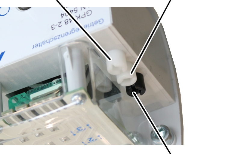
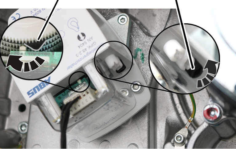
Outer
white adjusting screw |
Middle
white adjusting screw |
|
| |
|
|
Black adjusting screw (block adjustment) |
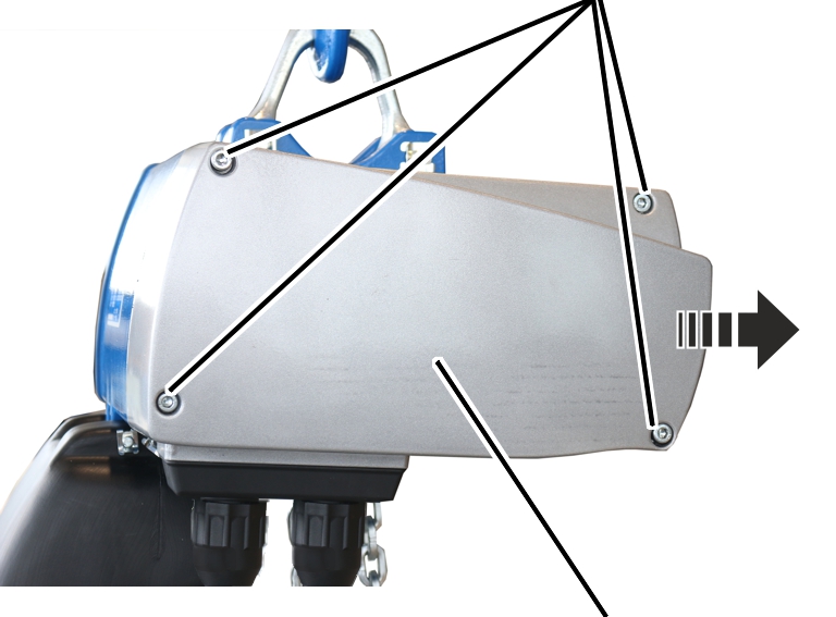
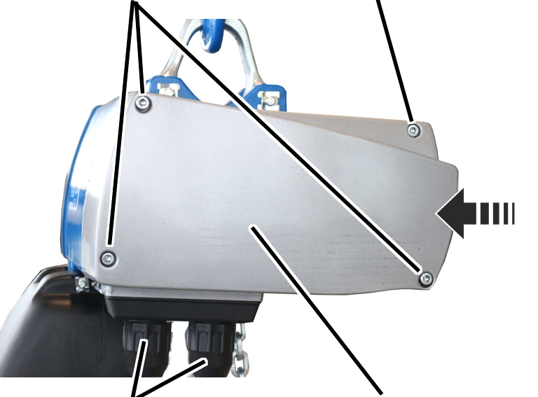
Unscrewing the motor cover
|
|
Fillister-head screws |
|
| |
|
|
Motor cover |
 Unscrew the motor cover from the
housing.
The fillister-head screws are secured by O-rings and thus do not fall out of the motor cover.
 Secure the motor cover.
The power supply must remain switched on while setting the switching points.
Setting the upper switching point
 Raise the load hook to the
desired switching point.
─ Bottom block or hook assembly must not come into contact with the housing.
─ The friction clutch must not be triggered.
|
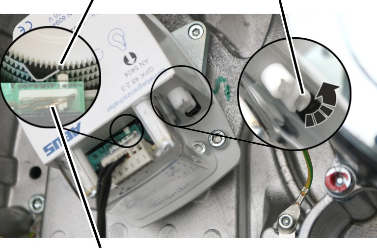
Control cam |
Middle | |
|
| ||
|
Microswitch |
| |
─ The upper switching point is set with the middle adjusting screw.
 If necessary: Turn the adjusting
screw until the control cam is to the left of the microswitch. It should not be
either directly on or to the right of the microswitch.
 Turn the adjusting screw to the
left until the control cam presses in an anti-clockwise direction against the
microswitch and an audible click is heard.
─ Turn the adjusting screw to the left (the control cam turns anticlockwise) to move the switching point downwards.
Checking the setting
 Lower the load hook.
 Raise the load hook at slow as
well as fast lifting speed and check that the load hook halts at the correct
hook position.
● The upper switching point is set.
Setting the lower switching point
 Lower the load hook to the
desired lower switching point.
─ The load hook must not come into contact with the floor of building.
─ The chain must not be slack.
─ The C-link in the chain box must not come into contact with the housing.
This would trigger the friction clutch and then damage it in regular movement.
─ The hook path (distance between the highest hook position and the lowest hook position) must not be greater than specified on the type plate.
|
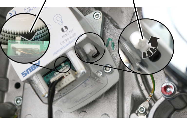
Control cam |
Outer |
|
| |
─ The lower switching point is set with the outer white adjusting screw.
 If necessary: Turn the adjusting
screw until the control cam is to the right of the microswitch. It must not be
on the left of the microswitch or exactly on it.
 Turn the adjusting screw to the
right until the control cam presses in a clockwise direction against the
microswitch and an audible click is heard.
─ Turn the adjusting screw to the right (the control cam turns clockwise) to move the switching point upwards.
─ Turn the adjusting screw to the left (the control cam turns anticlockwise) to move the switching point downwards.
Checking the setting
 Raise the load hook.
 Lower the load hook at slow as
well as fast lifting speed and check that the load hook halts at the correct
hook position.
● The lower switching point is set.
