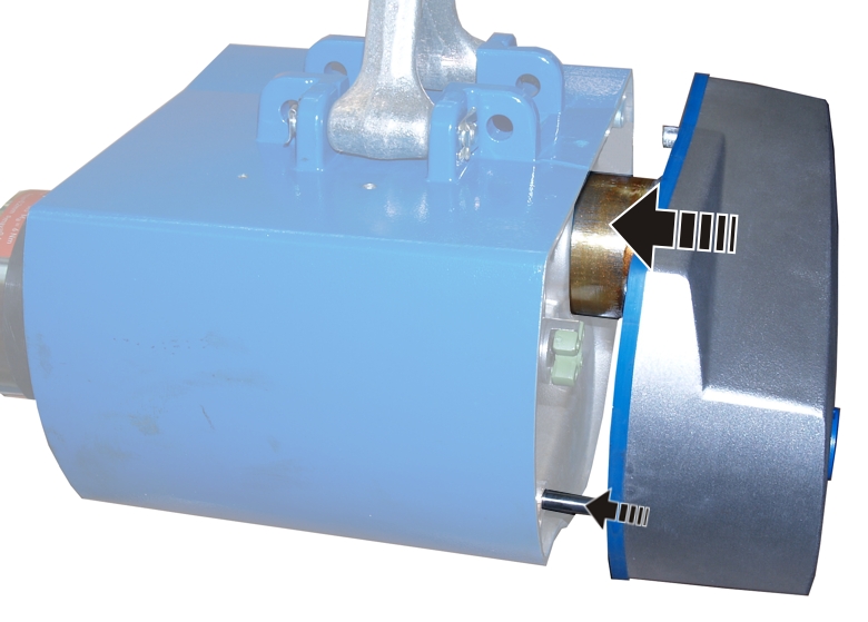
Output shaft
Gear unit dome
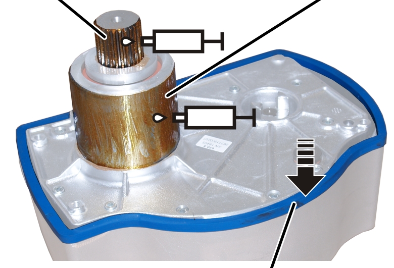
Seal
|
Output shaft |
Gear unit dome |
|
| |
|
|
Seal |
 Lubricate the gear unit dome and
output shaft.
Lubricate the gear unit dome and
output shaft.
Lubricant: “High temperature paste PBC 1574”. For details, see page 83.
Press on the seal.
|
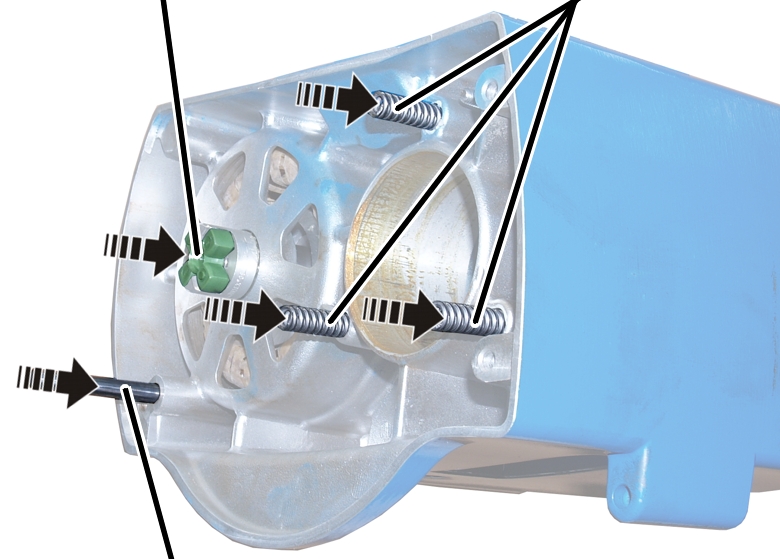
Gear rim |
Compression springs |
|
| |
|
Cylindrical pin |
|
Insert compression springs (2x,
3x, or 4x). Apply some grease if necessary.
Set the gear rim on the coupling
half.
Insert the cylindrical pin.
|
|
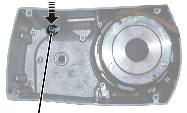
Push the gear unit into the
housing. The correct position of the gear unit is determined through the gear
unit dome and cylindrical pin.
|
| |
|
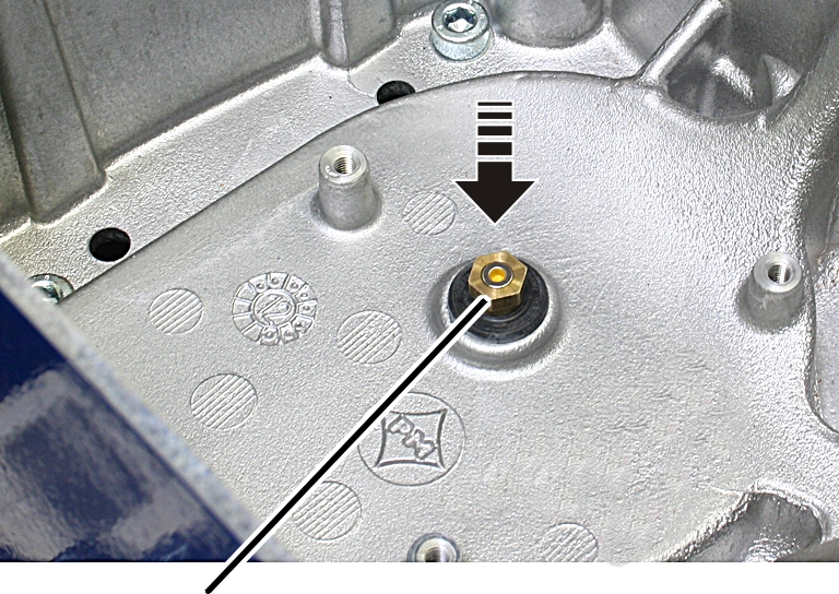
Locking screw |
|
Screw in the locking screw
(fillister-head screw).
|
Size |
Size and length |
Tightening torque |
|
GM2 |
M6x105 |
7 Nm |
|
GM4 |
M6x105 |
7 Nm |
|
GM6 |
M8x110 |
10 Nm |
|
GM8 |
M10x110 |
10 Nm |
|
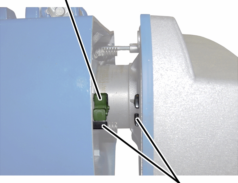
Gear rim |
|
|
| |
|
|
Coupling halves |
Check the position of the
coupling halves. The claws must be situated so that they grip precisely in the
gear rim.
If necessary:
Turn the coupling halves on the
gear unit until the claws are in the correct position.
|
|
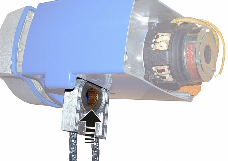
Push the chain guide from below
into the housing and hold it firmly.
|
|
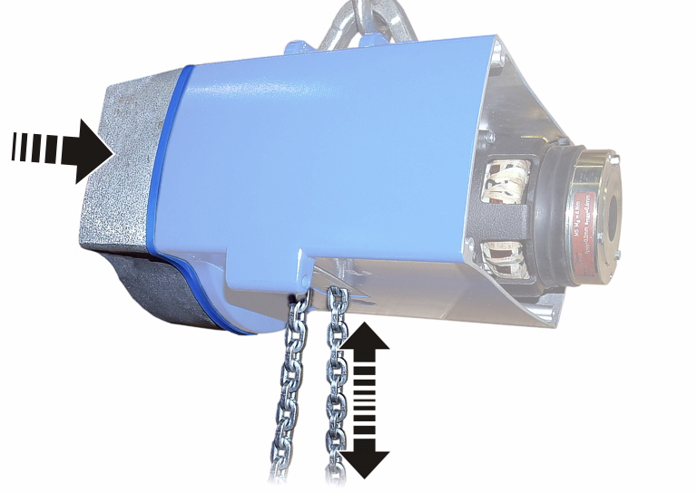
Push the gear unit into the
housing. Pull the chain slightly until the output shaft of the gear unit meshes
with the chain sprocket.
Tighten the fillister-head
screws (3x) in the housing.
|
Size |
Size and length |
Tightening torque |
|
GM2 |
M6x85 |
7 Nm |
|
GM4 |
M6x105 |
7 Nm |
|
GM6 |
M8x110 |
18 Nm |
|
GM8 |
M10x140 |
25 Nm |
|
| |
|
Magnet carrier |
|
Apply threadlocker (lightly) to
the thread of the magnet carrier.
Screw the magnet carrier in
place. 6 Nm.
|
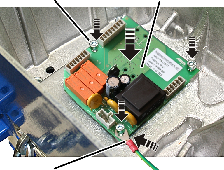
Fillister-head screws with ribs M5x10 |
Hoist limit switch PCB |
|
| |
|
Protective conductor |
|
Attach the protective conductor
to the fillister-head screw at the bottom right.
Place the hoist limit switch PCB
over the magnet carrier.
Use the fillister-head screws with
ribs M5x10 (3x) to screw the hoist limit switch PCB tight. 3 Nm.
Attach the couplings of the
hoist motor and brake to the pin multipoint connectors of the control in the
motor cover.
Only connect couplings and pin multipoint connectors of identical colour (orange and grey).
For the assignment, see page 92.
With electronic hoist limit
switch: Insert the connector on the hoist limit switch PCB.
|
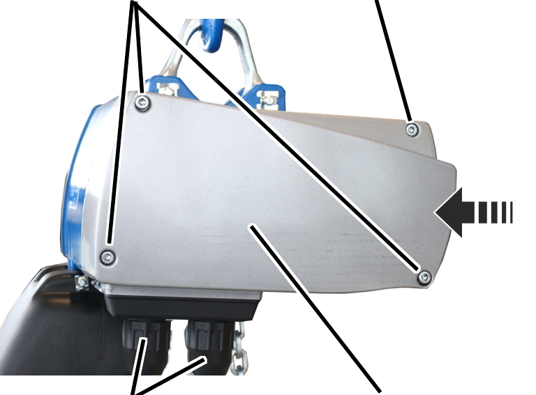
Long fillister-head screws |
Short fillister-head screw | |
|
| ||
|
Bayonet coupling |
Motor cover | |
Hold the motor cover on the
housing.
Note the different screw lengths
and screw in the fillister-head screws.
|
Size |
Size and length |
Number |
Tightening torque |
|
GM2 |
M5x65 |
3x |
4 Nm |
|
GM2 |
M5x45 |
1x |
4 Nm |
|
GM4 |
M5x60 |
3x |
4 Nm |
|
GM4 |
M5x50 |
1x |
4 Nm |
|
GM6 |
M8x110 |
3x |
15 Nm |
|
GM6 |
M8x60 |
1x |
15 Nm |
|
GM8 |
M10x95 |
3x |
20 Nm |
|
GM8 |
M10x50 |
1x |
20 Nm |
Insert the bayonet coupling of
the connection cable and the bayonet connector of the control cable. Due to a
notch, the plug-in connections will only fit together in one position.
Slide on and tighten the bayonet
nuts.
The illustrations show a chain box being installed on the GM6 chain hoist. Installation on a GM2 or GM4 chain hoist is very similar.
|
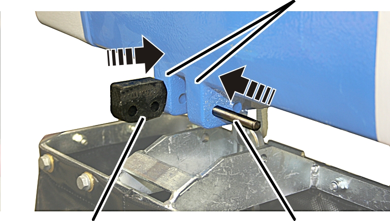
Bolt |
SL safety clip | |
|
| ||
|
|
Chain box | |
Place the chain in the chain
box.
Turn the chain box as shown in
the figure (slanted side facing outward).
Use the bolts to install the
chain box on the chain hoist.
─ For GM2: Use a bolt to fix the chain box to the chain hoist.
─ For GM4 and chain box with one hole: Use a bolt to fix the chain box to the chain hoist.
─ For GM4 and chain box with two holes: Use a bolt to fix the chain box to the chain hoist. Use the inner holes of the chain box. The outer holes remain free.
─ For GM6 and plastic chain box: Use two bolts to fix the chain box to the chain hoist.
Secure the bolts with the SL safety
clips (1x or 2x).
|
|
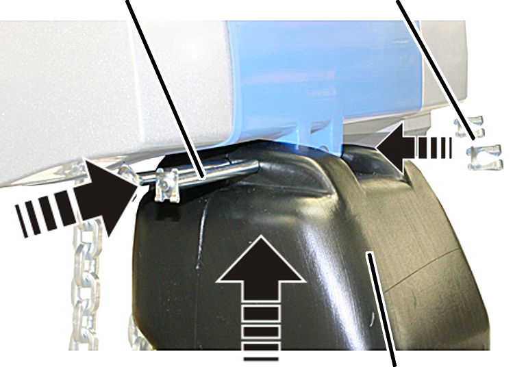
Suspension straps | |
|
| ||
|
Buffer |
Bolt | |
Turn the buffer as shown in the
figure (rounded side facing inward).
Push the buffer between the
suspension straps on the chain hoist.
Push the short bolt through the
outer holes of the suspension straps and the buffer.
The illustrations show a chain box being installed on the GM8 chain hoist. Installation on a GM6 chain hoist is very similar.
|
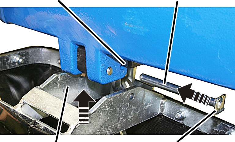
Inner hole |
Bolt |
|
| |
|
Chain box |
SL safety clip |
Place the chain in the chain
box.
Turn the chain box as shown in
the figure (bar facing outward).
Use the bolts to install the
chain box on the chain hoist.
─ For GM6 and chain box with metal frame: Use a bolt to fix the chain box to the chain hoist. Use the inner holes of the suspension strap. The outer holes of the suspension strap remain free.
─ For GM8: Use a bolt to fix the chain box to the chain hoist. Use the inner holes of the suspension strap. The buffer is fixed to the outer holes of the suspension straps.
Secure the bolts with the SL safety
clips (2x).
The electronic hoist limit
switch needs to be referenced again. See page 57.
Check the switching points
(upper and lower) and correct if necessary.
─ The saved switching points are retained after referencing and therefore do not need to be reset.
─ If the switching points are moved equally, all the switching points can be corrected at the same time by changing the reference point accordingly.