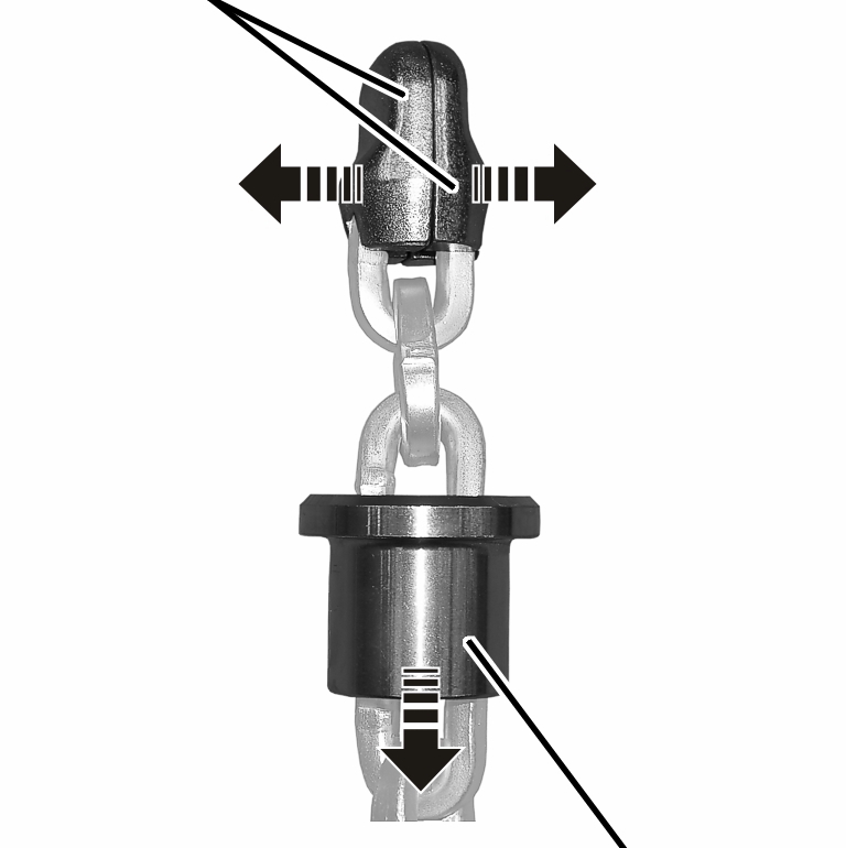
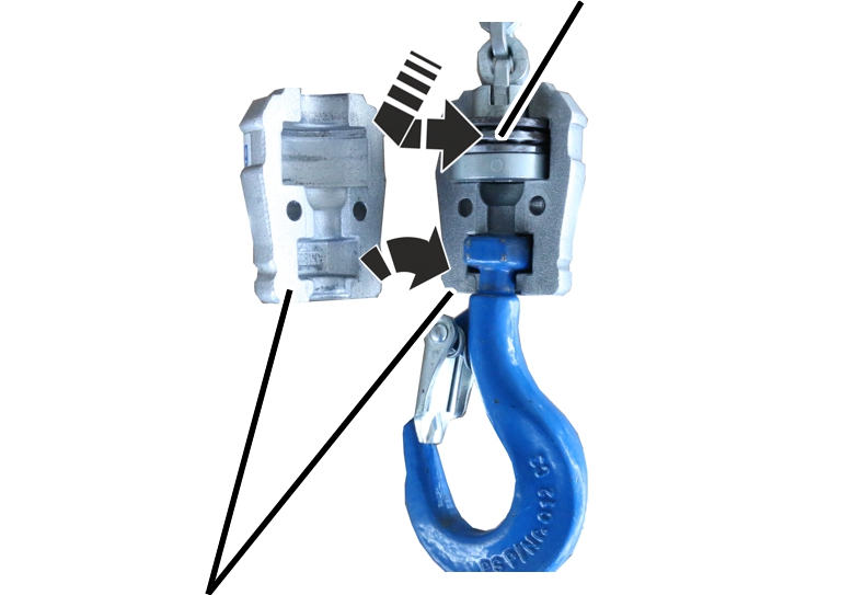
Bolt
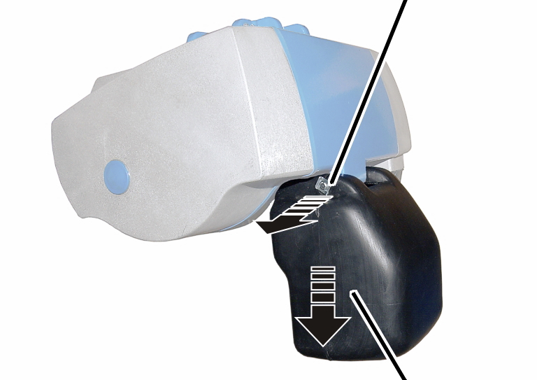
Chain box
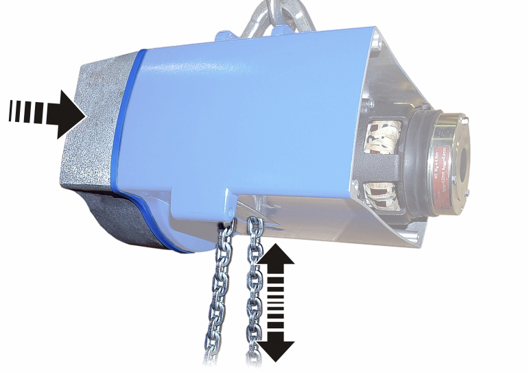
If the chain exhibits signs of wear or is too stretched from operation (see page 30), it must be exchanged.
Because of the modular construction of the chain hoist, the gear unit does not need to be disassembled in order to exchange the chain guide and chain sprocket. Instead, the gear unit is pulled off and the chain sprocket is then exposed.
|
|
Bolt | |
|
| ||
|
|
Chain box | |
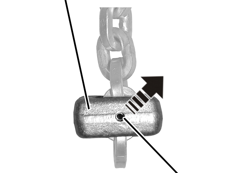
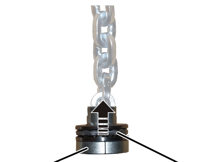
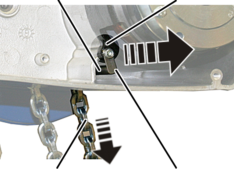
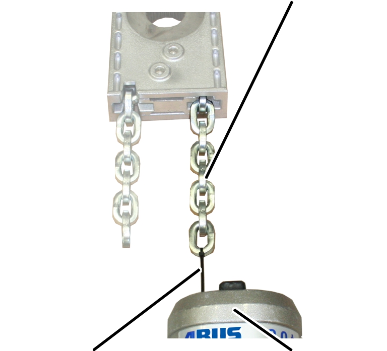
 Release the SL safety clip(s) (1x or 2x)
from the bolt.
Release the SL safety clip(s) (1x or 2x)
from the bolt.
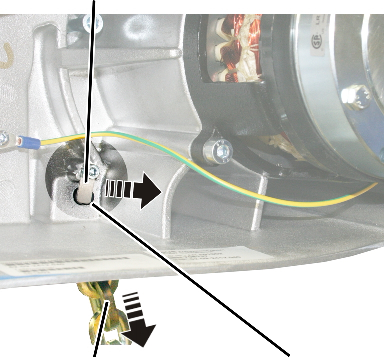
Hold the chain box firmly and
pull out the bolt(s) (1x or 2x).
Remove the chain box.
|
C-link |
|
|
| |
|
|
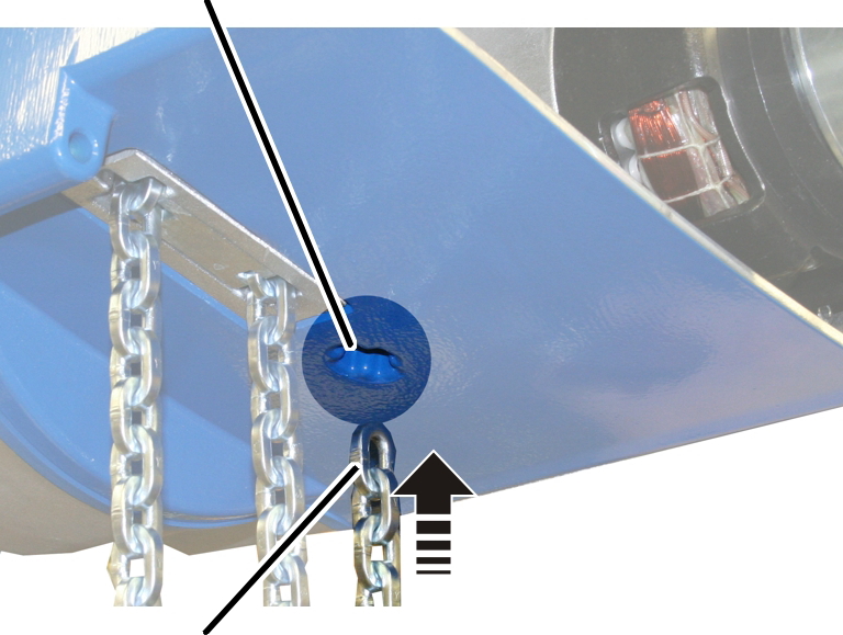
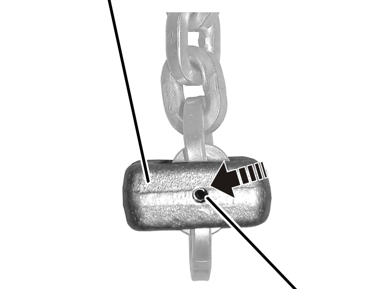
Tensioner sleeve |
Hammer the tensioner sleeve out
of the C-link.
|
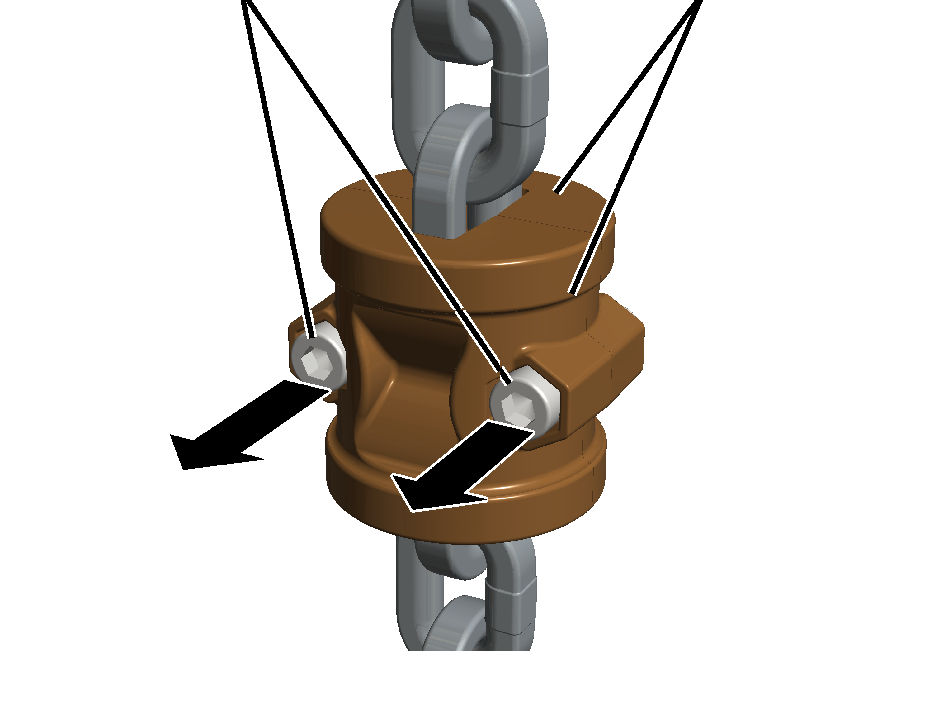
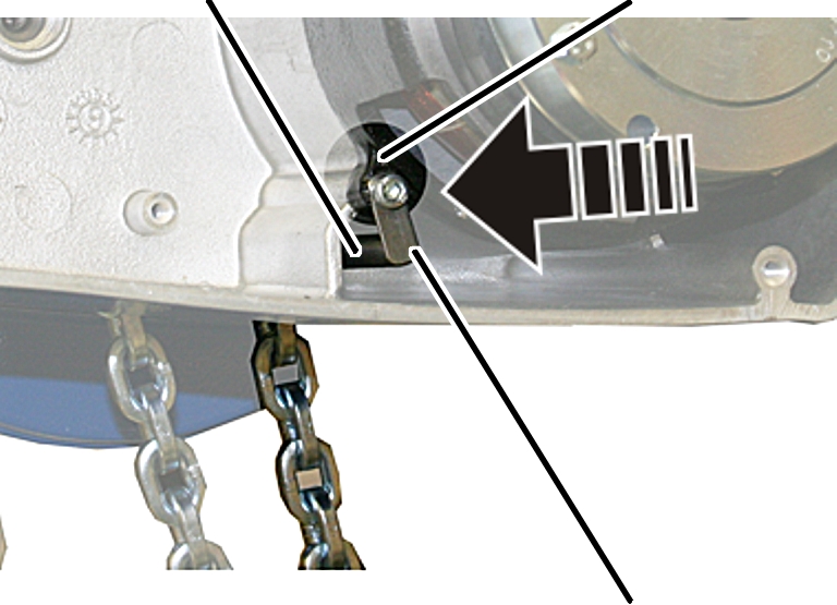
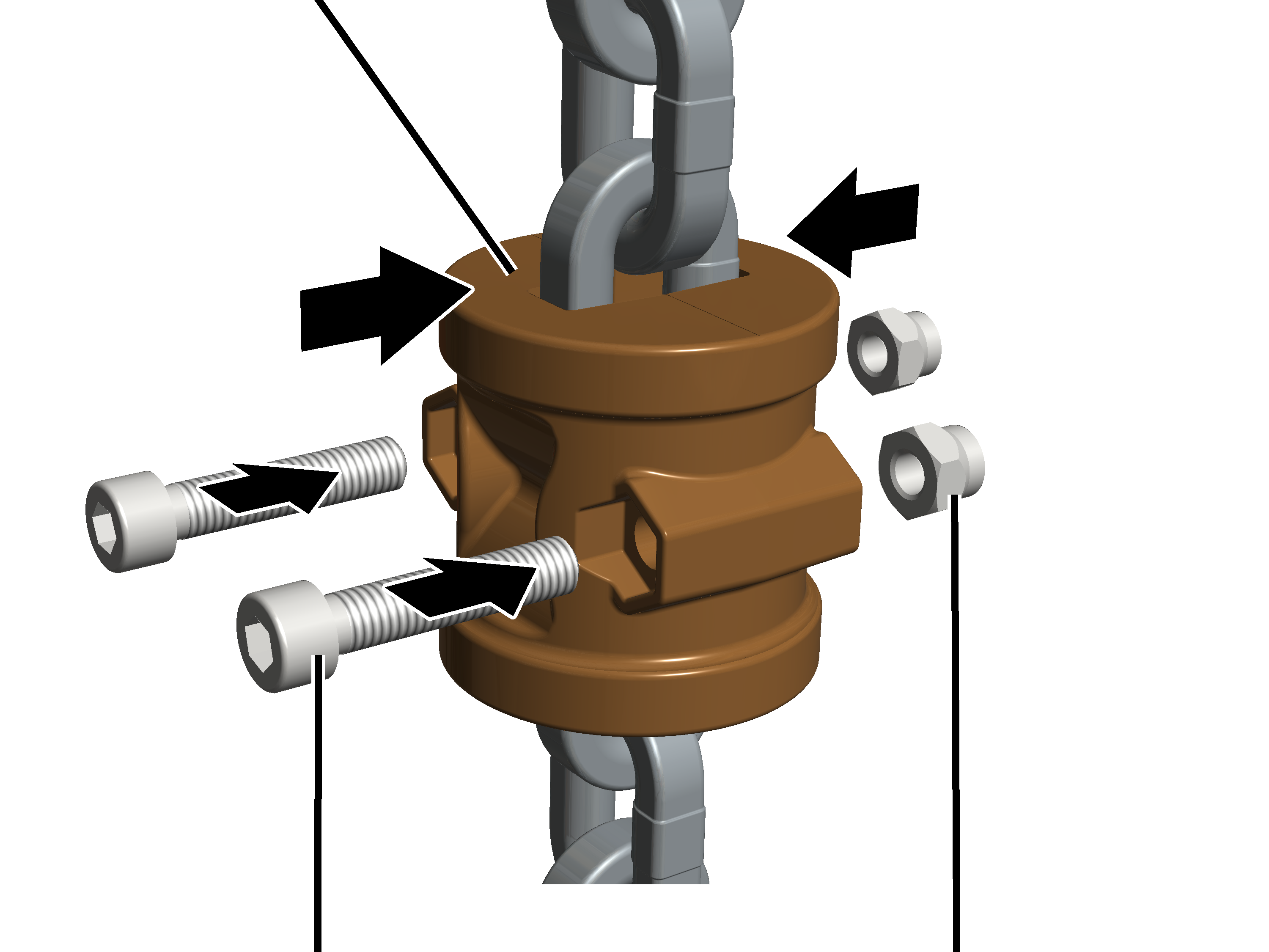
Fillister-head screw M6x30 |
C-link |
|
| |
Unscrew the fillister-head screw
M6x30 (2x).
Remove the halves of the C-link
from the chain.
|
| |
|
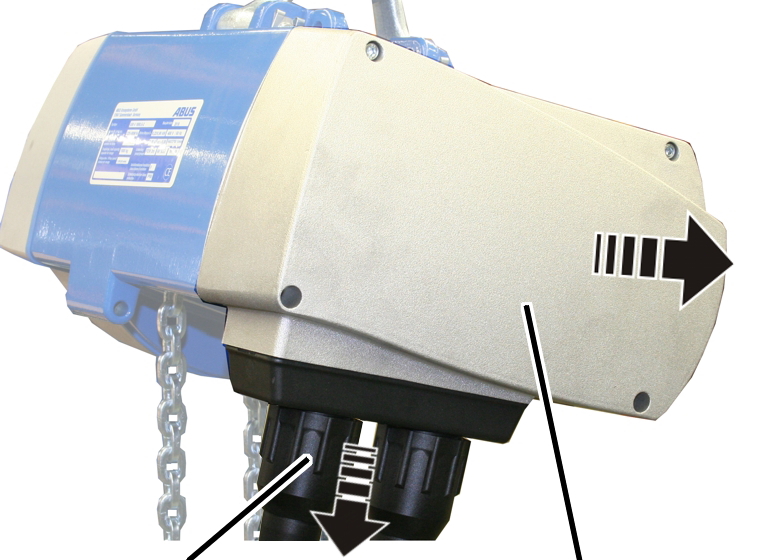
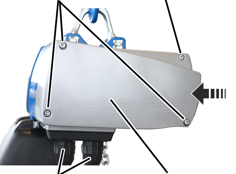
Bayonet nut |
Motor cover |
Release the bayonet nuts.
Detach the connection cable and
control cable.
Unscrew the motor cover from the
housing.
● The fillister-head screws are secured by O-rings and thus do not fall out of the motor cover.
Detach the couplings of the
hoist motor and brake from the control in the motor cover.
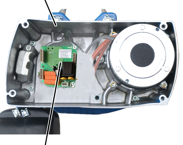
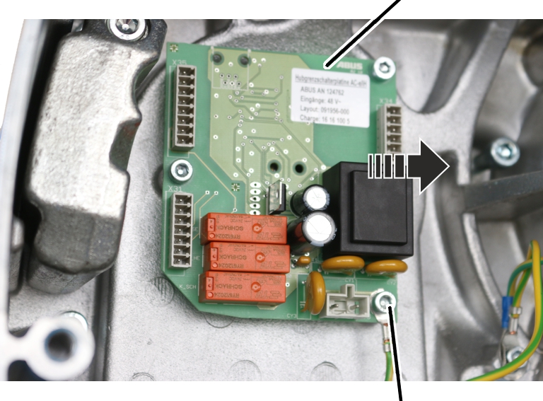
This work step is only applicable if the hoist limit switch PCB is visible in the housing:
|
Housing |
|
|
| |
|
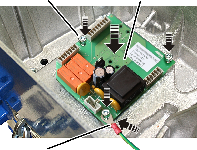
Hoist limit switch PCB |
|
|
|
Hoist limit switch PCB |
|
| |
|
|
Fillister-head screws with ribs M5x10 |
Pull the connector off the hoist
limit switch PCB.
Unscrew the fillister-head
screws with ribs M5x10 (3x).
Take the hoist limit switch PCB
out of the chain hoist.
|
| |
|
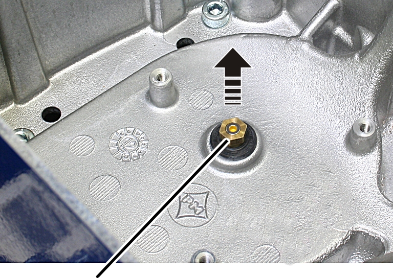
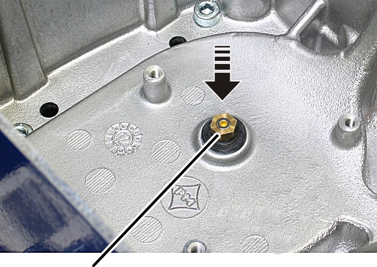
Magnet carrier |
|
Unscrew the magnet carrier.
|
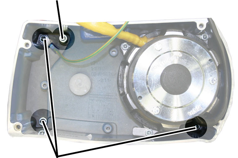
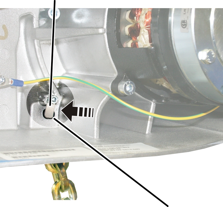
Locking screw |
| |
|
| ||
|
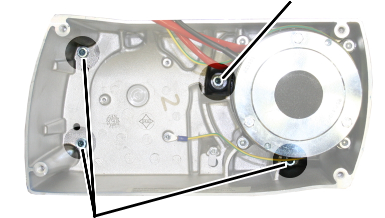
Fillister-head screws |
| |
Unscrew the fillister-head screws (3x).
Leave the locking screw
tightened.
It later ensures that the gear unit cannot not fall down.
|
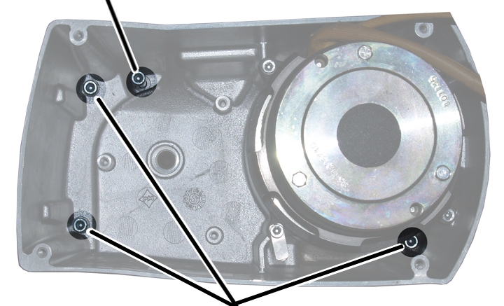
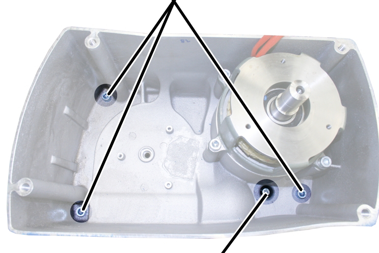
Locking screw |
|
|
| |
|
Fillister-head screws | |
Unscrew the fillister-head
screws (3x).
Leave the locking screw
tightened.
It later ensures that the gear unit cannot not fall down.
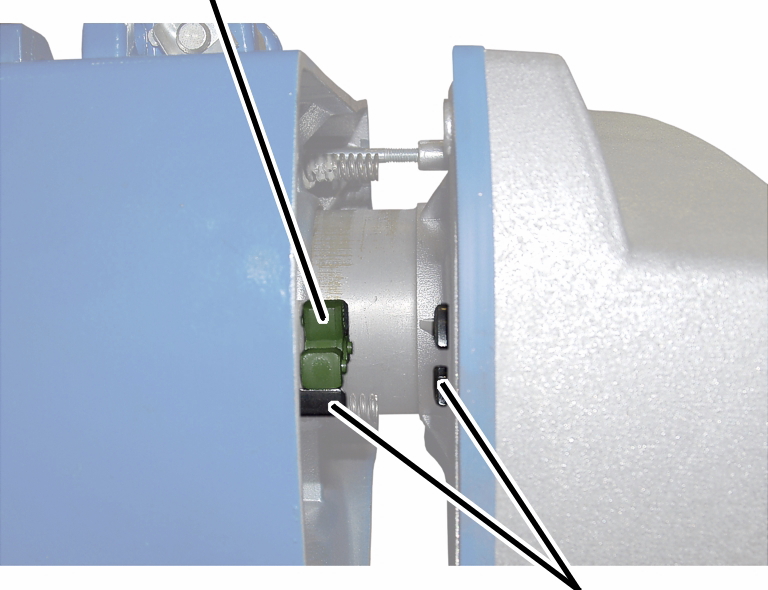
|
|
Locking screw |
|
| |
|
Fillister-head screws | |
Unscrew the fillister-head
screws (3x).
Leave the locking screw
tightened.
It later ensures that the gear unit cannot not fall down.
Tip:
The chain guide, chain and gear unit of the chain hoist are very heavy. Therefore unhook the chain hoist and remove the chain guide lying flat.
|
Fillister-head screws | |
|
| |
|
|
Locking screw |
Unscrew the fillister-head
screws (3x).
Leave the locking screw
tightened.
It later ensures that the gear unit cannot not fall down.
|
|
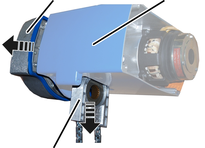
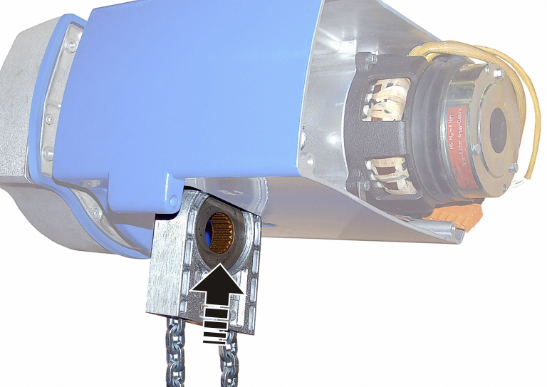
Caution - danger of injury! When pulling off the gear unit, the chain guide can fall down and injure people. Hold the chain guide firmly or otherwise secure it! |
|
Gear unit |
Housing |
|
| |
|
Chain guide |
|
Pull the gear unit from the
housing.
The locking screw secures the gear unit so that it need not be completely removed.
● The chain guide is now released.
Pull the entire chain guide
downward out of the housing.
|
| |
|
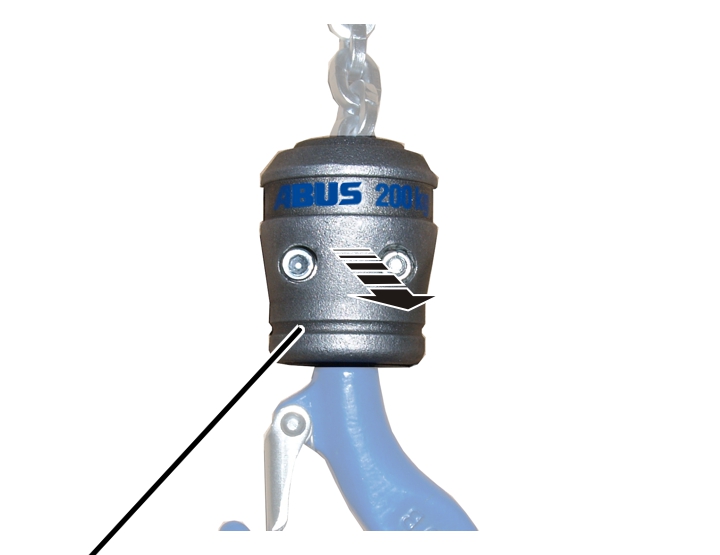
Hook assembly |
|
Screw the hook assembly
apart.
|
| |
|
Chain fastening element half |
Deep groove ball thrust bearing |
Push the three-piece deep groove
ball thrust bearing upward.
Remove both chain fastening
element halves from the chain.
Note the layout position of the deep
groove ball thrust bearing and remove it from the chain.
|
Bolt |
Brake bearing shield | |
|
| ||
|
Second fall |
Tab washer | |
Unscrew the tab washer on the brake
bearing shield.
Hold the second fall while
pulling out the bolt.
● The chain is now released.
Pull the chain out of the bottom block
on the load hook.
|
Tab washer |
|
|
| |
|
Second fall |
Bolt |
Unscrew the tab washer.
Hold the second fall while
pulling out the bolt.
● The chain is now released.
Pull the chain out of the bottom block
on the load hook.
|
| |
|
Flange sleeve |
|
Take the flange sleeve out of
the housing.
|
Chain fastening element halves |
|
|
| |
|
|
Flange sleeve |
Slide the flange sleeve
downward.
Remove both chain fastening
element halves from the chain.
Pull the chain out of the bottom block
on the load hook.
|
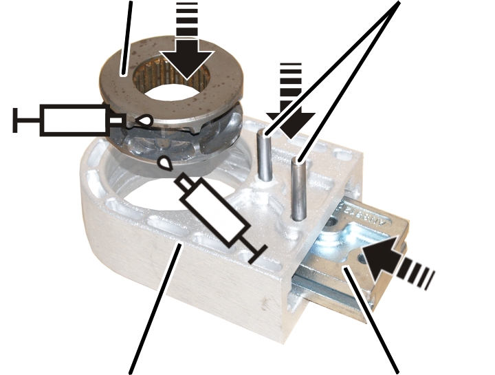
Chain sprocket |
Cylindrical pins |
|
| |
|
Chain guide |
Stripper |
Lubricate the new chain sprocket
as shown in the figure.
Lubricant: “High-Lub LT1 EP”. For details, see page 83.
Place the chain sprocket in the
new chain guide.
Push the stripper from below
into the chain guide.
Hammer in the cylindrical pin(s)
(1x or 2x).
Use exclusively ABUS genuine replacement chains. For technical data on the chain, see page 31.
|
| |
|
|
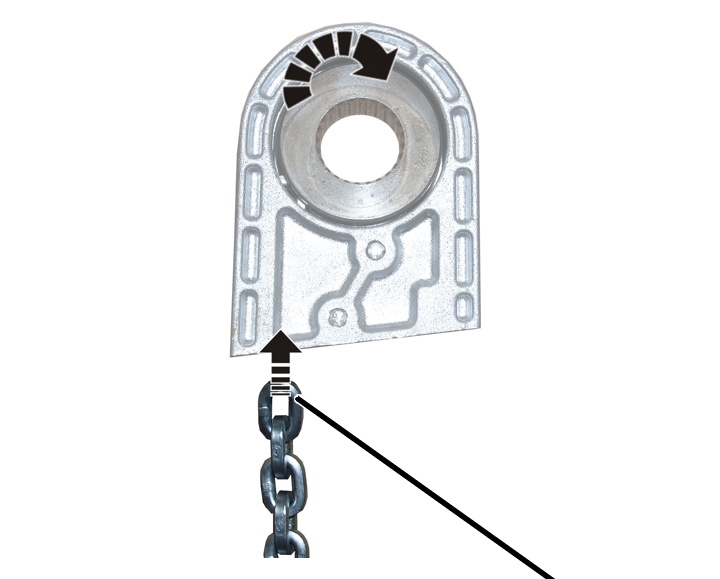
Vertical chain link |
Turn the chain as shown in the
figure. The first chain link should be pulled into the chain guide upright (on
edge).
The position of the weld seam to the chain link (toward the inside or the outside) does not need to be taken into account.
Pull the chain into the chain
guide.
|
Tip: Affix cable ties or wire to the end of the chain and use that to pull the chain through the chain guide.
|
|
Tip: Depending on the hook path, the new chain may be very heavy.
For easier installation:
| ||||||
|
|
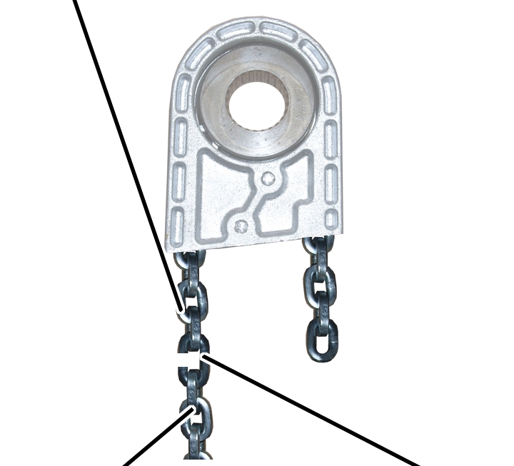
Second fall |
|
| |
|
Cable ties |
Bottom block |
Fasten cable ties to the end of
the second fall.
Turn the second fall so that it
is straight and pull the chain through the bottom block with the cable ties.
The second fall should not be allowed to twist as it is pulled through the bottom block.
|
Chain anchor point |
| |
|
| ||
|
Second fall |
| |
The chain should not be allowed to twist as it is pushed into the chain anchor point.
If necessary: Remove a single
chain link so that the second fall can be inserted straight.
|
|
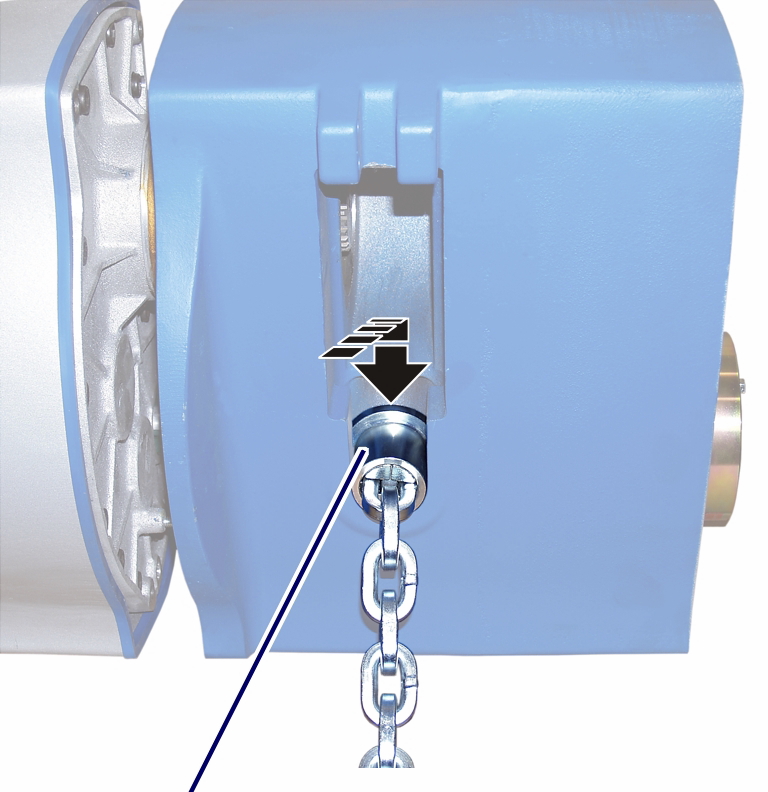
Danger from falling suspended load! The bolt can become loosened by vibration. The chain and load could fall, injuring or killing people. Bolt on the tab washer! |
|
Bolt |
Brake bearing shield |
|
| |
|
|
Tab washer |
● The second fall is now held by the bolt.
Bolt the tab washer with
fillister-head screw onto the brake bearing shield.
|
Size |
Type and length |
Tightening torque |
|
GM2 |
M5x20 |
4 Nm |
|
GM4 |
M5x20 |
4 Nm |
|
Chain anchor point |
| |
|
| ||
|
Second fall |
| |
Turn the chain so that it is
straight and push the second fall from below into the chain anchor point.
The chain should not be allowed to twist as it is pushed into the chain anchor point.
If necessary: Remove a single
chain link so that the second fall can be inserted straight.
|
|
Danger from falling suspended load! The bolt can become loosened by vibration. The chain and load could fall, injuring or killing people. Bolt on the tab washer! |
|
Tab washer |
|
|
| |
|
|
Bolt |
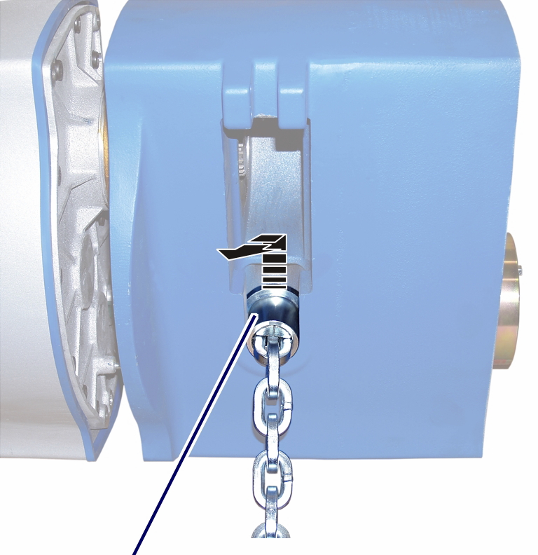
Insert the bolt.
● The second fall is now held by the bolt.
Bolt on the tab washer with the
M5x10 fillister-head screw. 3 Nm.
|
|
Chain fastening element halves |
|
| |
|
|
Flange sleeve |
Push the flange sleeve onto the
second fall of the chain.
Place the chain fastening
element halves from both sides on the last chain link and slide a flange sleeve
over it.
|
| |
|
Flange sleeve |
|
Push the flange sleeve into the
housing.
|
Gear rim |
|
|
| |
|
|
Coupling halves |
Check the position of the
coupling halves. The claws must be situated so that they grip precisely in the
gear rim.
If necessary:
Turn the coupling halves on the
gear unit until the claws are in the correct position.
|
|
Push the chain guide from below
into the housing and hold it firmly.
|
|
Push the gear unit into the
housing. Pull the chain slightly until the output shaft of the gear unit meshes
with the chain sprocket.
Tighten the fillister-head
screws (3x) in the housing.
|
Size |
Size and length |
Tightening torque |
|
GM2 |
M6x85 |
7 Nm |
|
GM4 |
M6x105 |
7 Nm |
|
GM6 |
M8x110 |
18 Nm |
|
GM8 |
M10x140 |
25 Nm |
|
| |
|
|
Inside chain end |
Use the inside end of the chain
to install the load hook.
|
Ball bearing race (large inner diameter) |
Ball bearing cage |
|
| |
|
Ball bearing race (small inner diameter) |
|
Push the deep groove ball thrust
bearing onto the chain facing the right direction: First push on the ball
bearing race with the larger inner diameter (smoothed), then the ball bearing
cage, then the ball bearing race with the smaller inner diameter (not
smoothed).
Place the chain fastening
element halves on the chain from both sides.
|
|
Deep groove ball thrust bearing |
|
| |
|
|
Chain fastening element halves |
Push the deep groove ball thrust
bearing over the chain fastening element halves.
Lubricate the deep groove ball
thrust bearing.
Lubricant: “High-Lub LT1 EP”. For details, see page 83.
|
|
Deep groove ball thrust bearing with chain fastening element halves |
|
| |
|
Hook assembly |
|
Insert the deep groove ball
thrust bearing with chain fastening element halves into one half of the hook
assembly.
Assemble the hook assembly.
Bolt the hook assembly with the
fillister-head screw and self-locking nut (2x).
|
Size |
Size and length |
Tightening torque |
|
GM2 |
M6x25 |
10 Nm |
|
GM4 |
M6x25 |
10 Nm |
|
GM6 |
M6x45 |
12 Nm |
|
GM8 |
M8x50 |
30 Nm |
|
| |
|
Magnet carrier |
|
Apply threadlocker (lightly) to
the thread of the magnet carrier.
Screw the magnet carrier in
place. 6 Nm.
|
Fillister-head screws with ribs M5x10 |
Hoist limit switch PCB |
|
| |
|
Protective conductor |
|
Attach the protective conductor
to the fillister-head screw at the bottom right.
Place the hoist limit switch PCB
over the magnet carrier.
Use the fillister-head screws with
ribs M5x10 (3x) to screw the hoist limit switch PCB tight. 3 Nm.
Attach the couplings of the
hoist motor and brake to the pin multipoint connectors of the control in the
motor cover.
Only connect couplings and pin multipoint connectors of identical colour (orange and grey).
For the assignment, see page 92.
With electronic hoist limit
switch: Insert the connector on the hoist limit switch PCB.
|
Long fillister-head screws |
Short fillister-head screw | |
|
| ||
|
Bayonet coupling |
Motor cover | |
Hold the motor cover on the
housing.
Note the different screw lengths
and screw in the fillister-head screws.
|
Size |
Size and length |
Number |
Tightening torque |
|
GM2 |
M5x65 |
3x |
4 Nm |
|
GM2 |
M5x45 |
1x |
4 Nm |
|
GM4 |
M5x60 |
3x |
4 Nm |
|
GM4 |
M5x50 |
1x |
4 Nm |
|
GM6 |
M8x110 |
3x |
15 Nm |
|
GM6 |
M8x60 |
1x |
15 Nm |
|
GM8 |
M10x95 |
3x |
20 Nm |
|
GM8 |
M10x50 |
1x |
20 Nm |
Insert the bayonet coupling of
the connection cable and the bayonet connector of the control cable. Due to a
notch, the plug-in connections will only fit together in one position.
Slide on and tighten the bayonet
nuts.
|
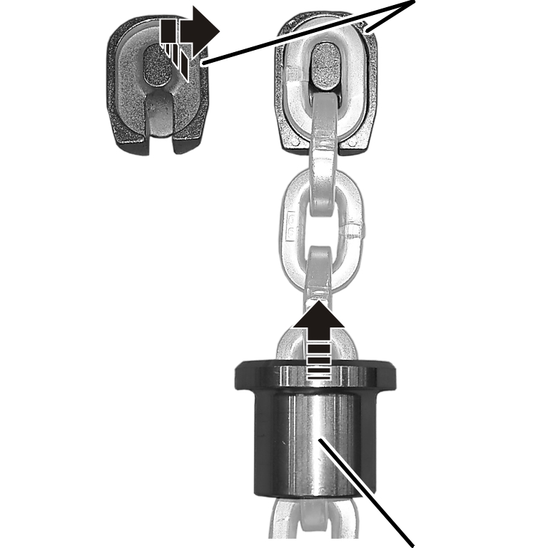
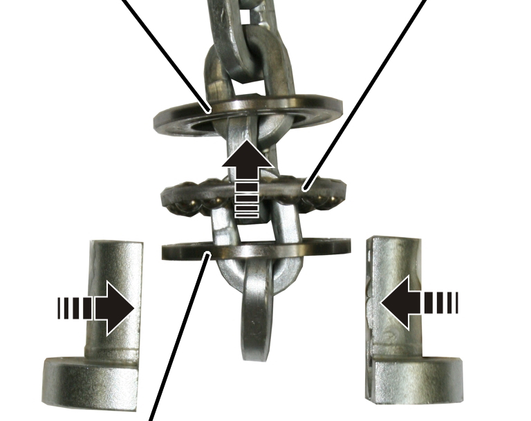
C-link |
|
|
| |
|
|
Tensioner sleeve |
Use the outside end of the chain
to install the C-link.
Turn the C-link so that the
opening, when installed, points in the direction of the inner fall (the fall
under load).
Push the C-link onto the
second-last or third-last chain link (depending on the orientation from the
previous step).
Hammer the tensioner sleeve into
the C-link.
Place the chain in the chain
box.
Check whether the chain
completely fits in the chain box. If the chain box is too small, contact ABUS
Service. See page 89.
|
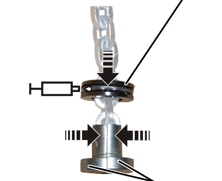
C-link |
|
|
| |
|
Fillister-head screw M6x30 |
Self-locking nut |
Use the outside end of the chain
to install the C-link.
Turn the C-link so that the
heads of the fillister-head screws point in the direction of the inner fall (the
fall under load) when installed.
Place the halves of the C-link
on the second-last or third-last chain link (depending on the orientation from
the previous step).
Tighten the C-link with the
fillister-head screws M6x30 (2x) and self-locking nuts M6 (2x). 10 Nm.
Place the chain in the chain
box.
Check whether the chain
completely fits in the chain box. If the chain box is too small, contact ABUS
Service. See page 89.