Air gap (between magnet body and anchor plate)
Brake lining thickness
Magnet body and anchor plate
Brake rotor with brake lining
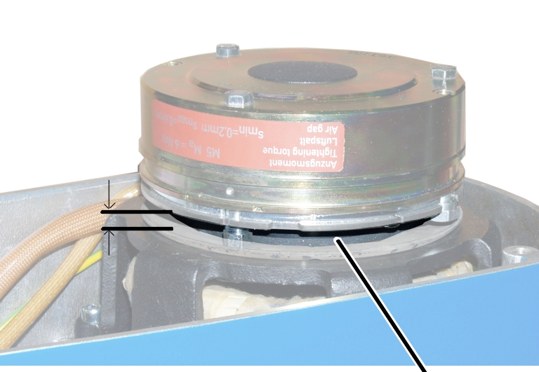
To check the brake, a measurement is made of the air gap between magnet body and anchor plate, as well as the brake lining thickness.
|
Air gap (between magnet body and anchor plate) |
Brake lining thickness |
|
| |
|
Magnet body and anchor plate |
Brake rotor with brake lining |
|
Size |
Air gap target value |
Maximum air gap |
Minimum air gap |
|
GM2 |
0.25 mm |
0.6 mm |
0.2 mm |
|
GM4 |
0.3 mm |
0.6 mm |
0.2 mm |
|
GM6 |
0.35 mm |
0.6 mm |
0.3 mm |
|
GM8 |
0.35 mm |
0.6 mm |
0.3 mm |
This is the point at which the air gap must be readjusted at the latest. If the minimum lining thickness has been reached, the brake rotor must be replaced.
|
| |
|
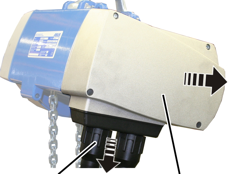
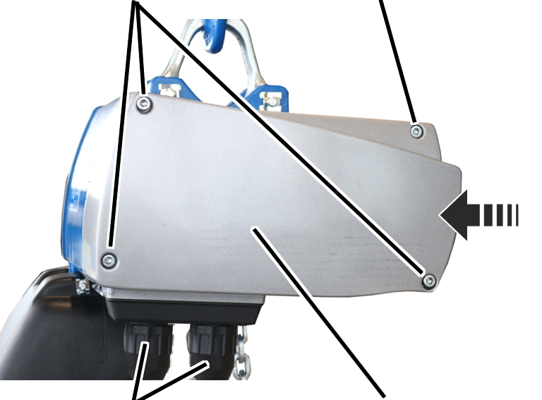
Bayonet nut |
Motor cover |
 Detach the connection cable and control cable.
Unscrew the motor cover from the housing.
● The fillister-head screws are secured by O-rings and thus do not fall out of the motor cover.
Detach the couplings of the hoist motor and brake from the control in
the motor cover.
|
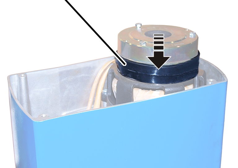
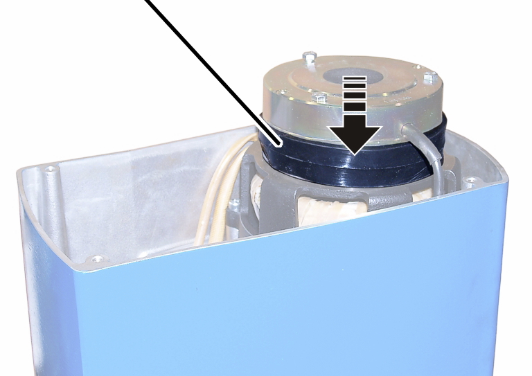
Dust guard ring |
|
|
| |
Pull off the dust guard ring.
|
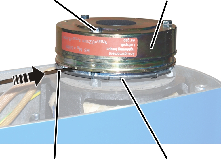
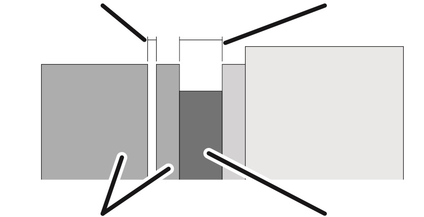
Hexagon head screw |
Magnet body | |
|
| ||
|
Feeler gauge |
Anchor plate | |
If the air gap has reached the maximum width of the operating range, adjust the brake. See page 64.
|
Size |
Air gap target value |
Maximum air gap |
Minimum air gap |
|
GM2 |
0.25 mm |
0.6 mm |
0.2 mm |
|
GM4 |
0.3 mm |
0.6 mm |
0.2 mm |
|
GM6 |
0.35 mm |
0.6 mm |
0.3 mm |
|
GM8 |
0.35 mm |
0.6 mm |
0.3 mm |
If the width of the air gap is within the permitted range but usage behaviour leads to the expectation that the air gap will be wider than permitted before the next regular inspection, the air gap must be readjusted now.
Repeat the steps for all hexagon head
screws (3x).
Clean the entire brake with compressed air.
|
| |
|
|
Brake rotor |
Check the thickness of the brake lining with a calliper.
|
Size |
Brake lining thickness, new |
Brake lining thickness, minimum |
|
GM2 |
7.5 mm |
4.5 mm |
|
GM4 |
8.5 mm |
5.5 mm |
|
GM6 |
10.5 mm |
7.5 mm |
|
GM8 |
10.5 mm |
7.5 mm |
If the brake rotor is thinner than permitted, replace the brake
rotor. See page 69.
|
Dust guard ring |
|
|
| |
Pull the dust guard ring over the brake.
Attach the couplings of the hoist motor and brake to the pin
multipoint connectors of the control in the motor cover.
Only connect couplings and pin multipoint connectors of identical colour (orange and grey).
For the assignment, see page 92.
With electronic hoist limit switch: Insert the connector on the hoist
limit switch PCB.
|
Long fillister-head screws |
Short fillister-head screw | |
|
| ||
|
Bayonet coupling |
Motor cover | |
Hold the motor cover on the housing.
Note the different screw lengths and screw in the fillister-head
screws.
|
Size |
Size and length |
Number |
Tightening torque |
|
GM2 |
M5x65 |
3x |
4 Nm |
|
GM2 |
M5x45 |
1x |
4 Nm |
|
GM4 |
M5x60 |
3x |
4 Nm |
|
GM4 |
M5x50 |
1x |
4 Nm |
|
GM6 |
M8x110 |
3x |
15 Nm |
|
GM6 |
M8x60 |
1x |
15 Nm |
|
GM8 |
M10x95 |
3x |
20 Nm |
|
GM8 |
M10x50 |
1x |
20 Nm |
Insert the bayonet coupling of the connection cable and the bayonet
connector of the control cable. Due to a notch, the plug-in connections will
only fit together in one position.
Slide on and tighten the bayonet nuts.