Only for GM2, GM4 and GM6 with direct control
Opening the chain hoist
|
| |
|
Bayonet nut |
Motor cover |
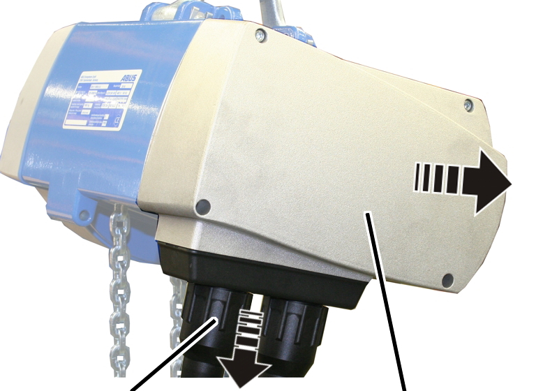
 Release the bayonet nuts.
Detach the connection cable and
control cable.
Unscrew the motor cover from the
housing.
● The fillister-head screws are secured by O-rings and thus do not fall out of the motor cover.
Detach the couplings of the
hoist motor and brake from the control in the motor cover.
Replacing the fuses
|
Cover |
|
|
| |
|
Fuse holder |
Safety device |
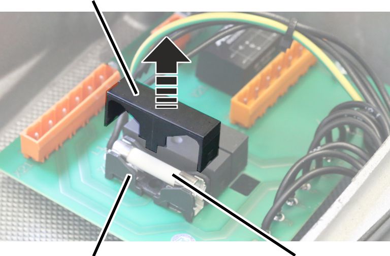
Pull the cover upwards and off the fuse
holder.
Replace the fuse.
Use 3x ceramic tube fuse 32x6.3, 10A, slow-blow.
Fit the cover onto the fuse
holder and lock in place.
Connecting the chain hoist
Attach the couplings of the
hoist motor and brake to the pin multipoint connectors of the control in the
motor cover.
Only connect couplings and pin multipoint connectors of identical colour (orange and grey).
For the assignment, see page 92.
With electronic hoist limit
switch: Insert the connector on the hoist limit switch PCB.
Closing the chain hoist
|
Long fillister-head screws |
Short fillister-head screw | |
|
| ||
|
Bayonet coupling |
Motor cover | |
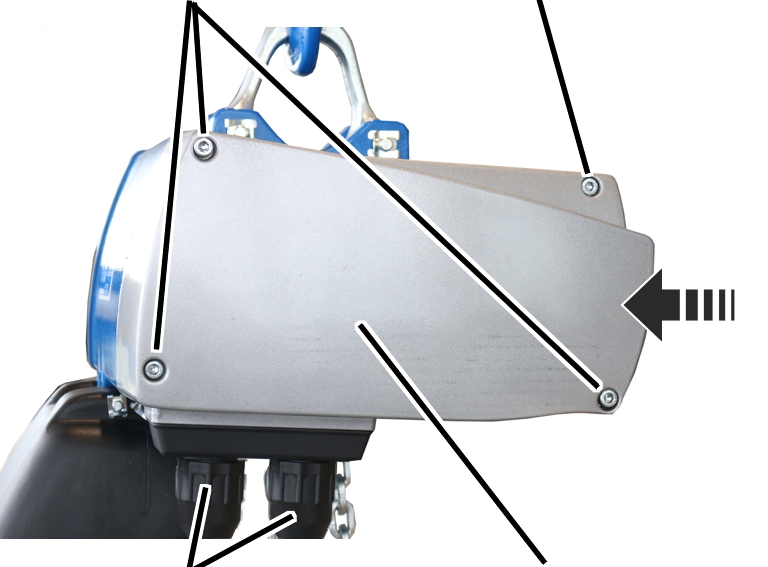
Hold the motor cover on the
housing.
Note the different screw lengths
and screw in the fillister-head screws.
|
Size |
Size and length |
Number |
Tightening torque |
|
GM2 |
M5x65 |
3x |
4 Nm |
|
GM2 |
M5x45 |
1x |
4 Nm |
|
GM4 |
M5x60 |
3x |
4 Nm |
|
GM4 |
M5x50 |
1x |
4 Nm |
|
GM6 |
M8x110 |
3x |
15 Nm |
|
GM6 |
M8x60 |
1x |
15 Nm |
|
GM8 |
M10x95 |
3x |
20 Nm |
|
GM8 |
M10x50 |
1x |
20 Nm |
Insert the bayonet coupling of
the connection cable and the bayonet connector of the control cable. Due to a
notch, the plug-in connections will only fit together in one position.
Slide on and tighten the bayonet
nuts.