Comply
with occupational health and safety requirements.
Comply
with occupational health and safety requirements.If the wheel is damaged or worn, it must be replaced by a new wheel.
The figures show the disassembly of a size 130 wheel. The removal of larger wheels does not essentially differ from this.
Comply
with occupational health and safety requirements.
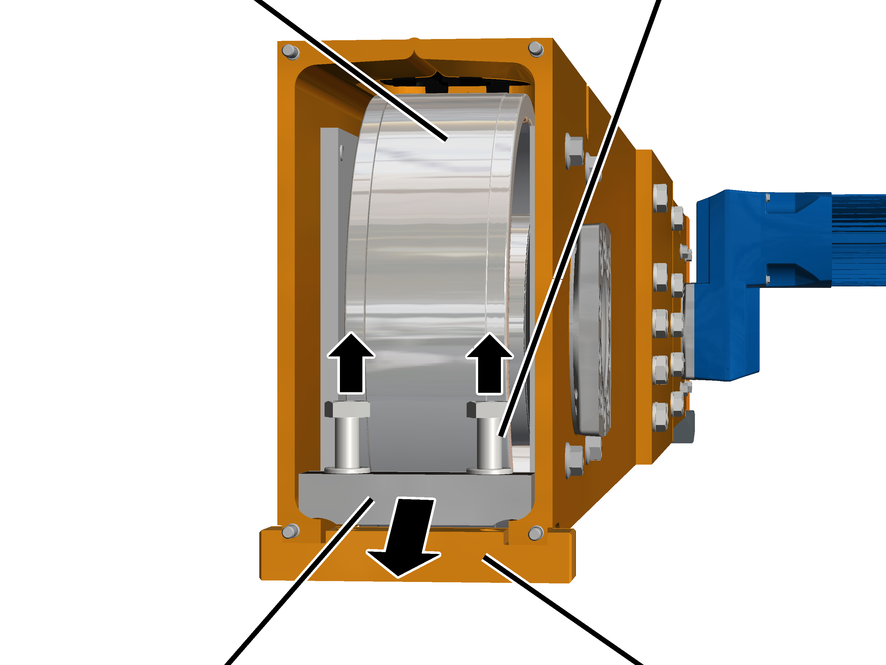
Prop up the end carriage close
to the wheel.
|
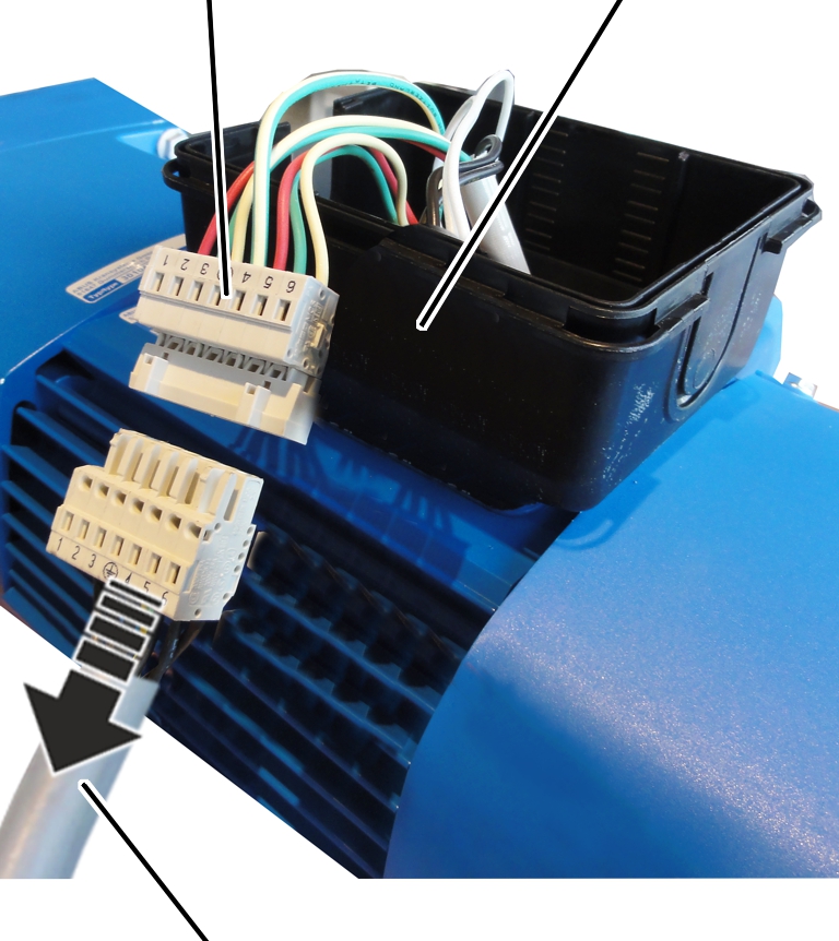
Connector housing | ||
|
| ||
|
Connection cable |
| |
Open the connector housing to
the drive.
Disconnect the connection cable
from the coupler plug.
Determine the weight of the
drive. See the ABUS Drive product manual.
 Secure the drive so that the
weight can be held safely and the output shaft will not be subject to load (e.g.
insert in round sling).
Secure the drive so that the
weight can be held safely and the output shaft will not be subject to load (e.g.
insert in round sling).
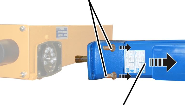
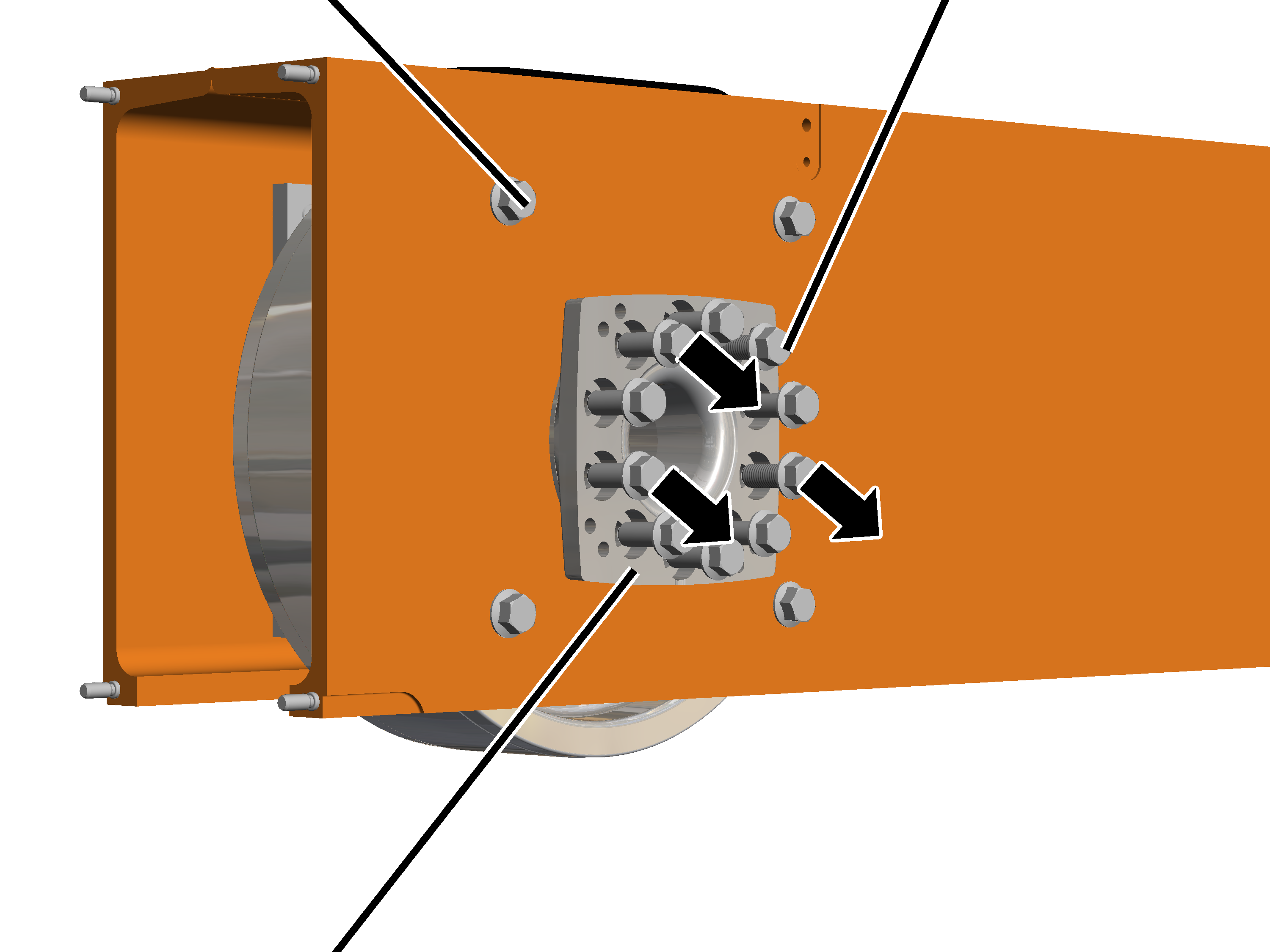
|
Screws | |
|
| |
|
|
Crane travel drive |
Unscrew and remove screws
(4x).
Pull out the crane travel
drive.
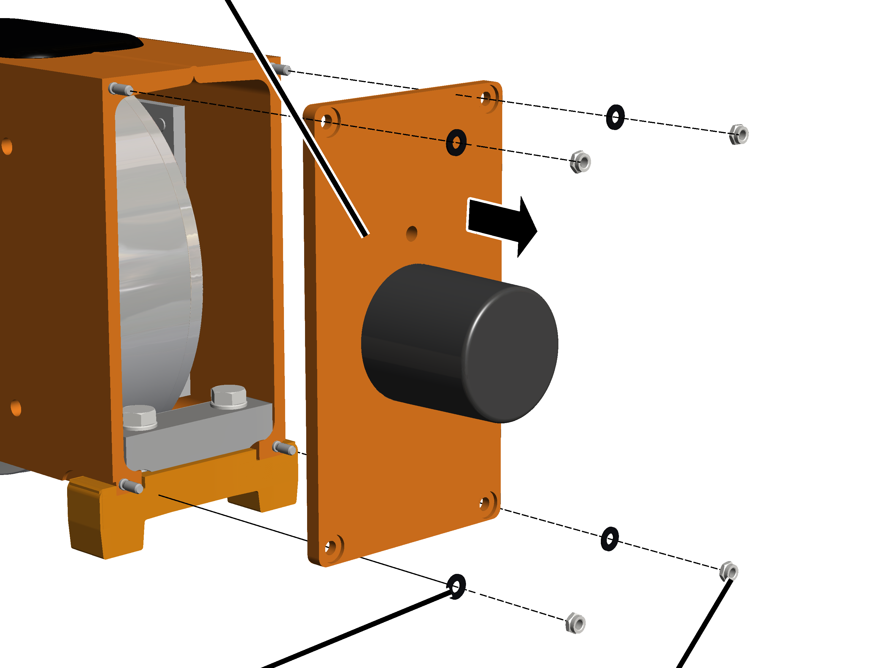
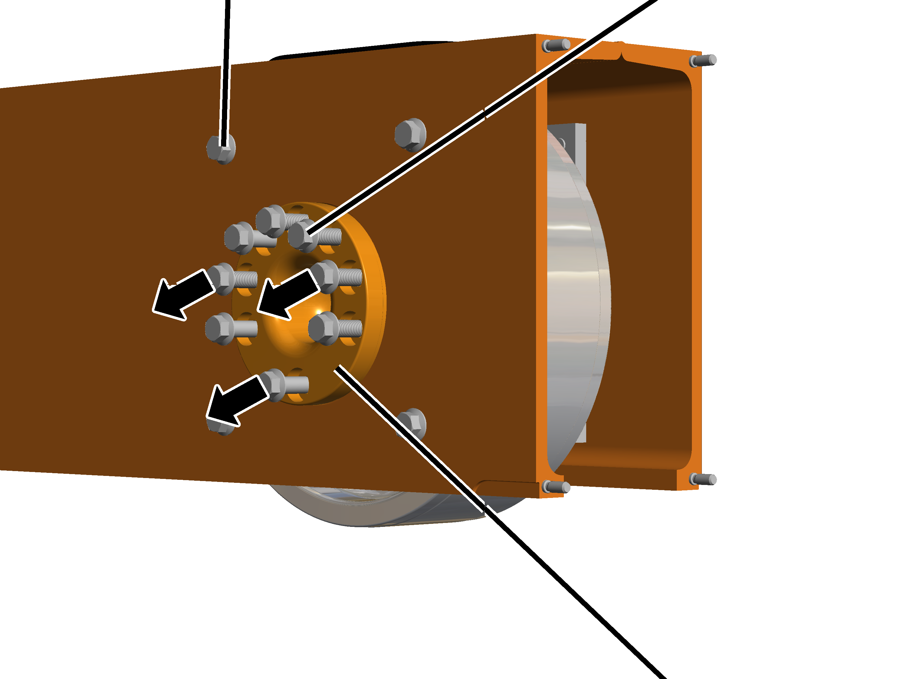
|
Buffer plate |
|
|
| |
|
Plastic washer |
Self-locking nut |
Unscrew the self-locking nuts (4x).
From size 160: Remove the
plastic washers (4x).
Remove the buffer plate.
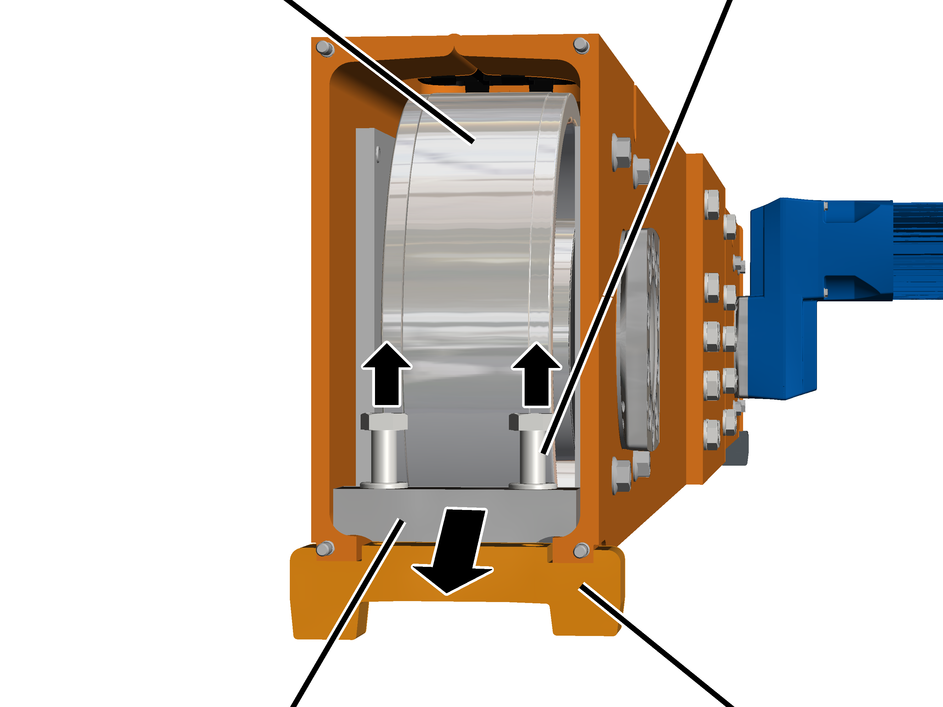
|
Wheel |
Screw M20 | |
|
| ||
|
Clamping element |
Derailing protection device | |
Undo the M20 screws.
Remove the derailing protection
device.
Take out the clamping
element.
|
Wheel |
Screw M20 | |
|
| ||
|
Clamping element |
Clamping piece | |
Undo the M20 screws.
Remove the clamping piece.
Take out the clamping
element.
|
Retaining screw |
Rib screws | |
|
| ||
|
Bearing flange |
| |
|
Retaining screw |
Rib screws | |
|
| ||
|
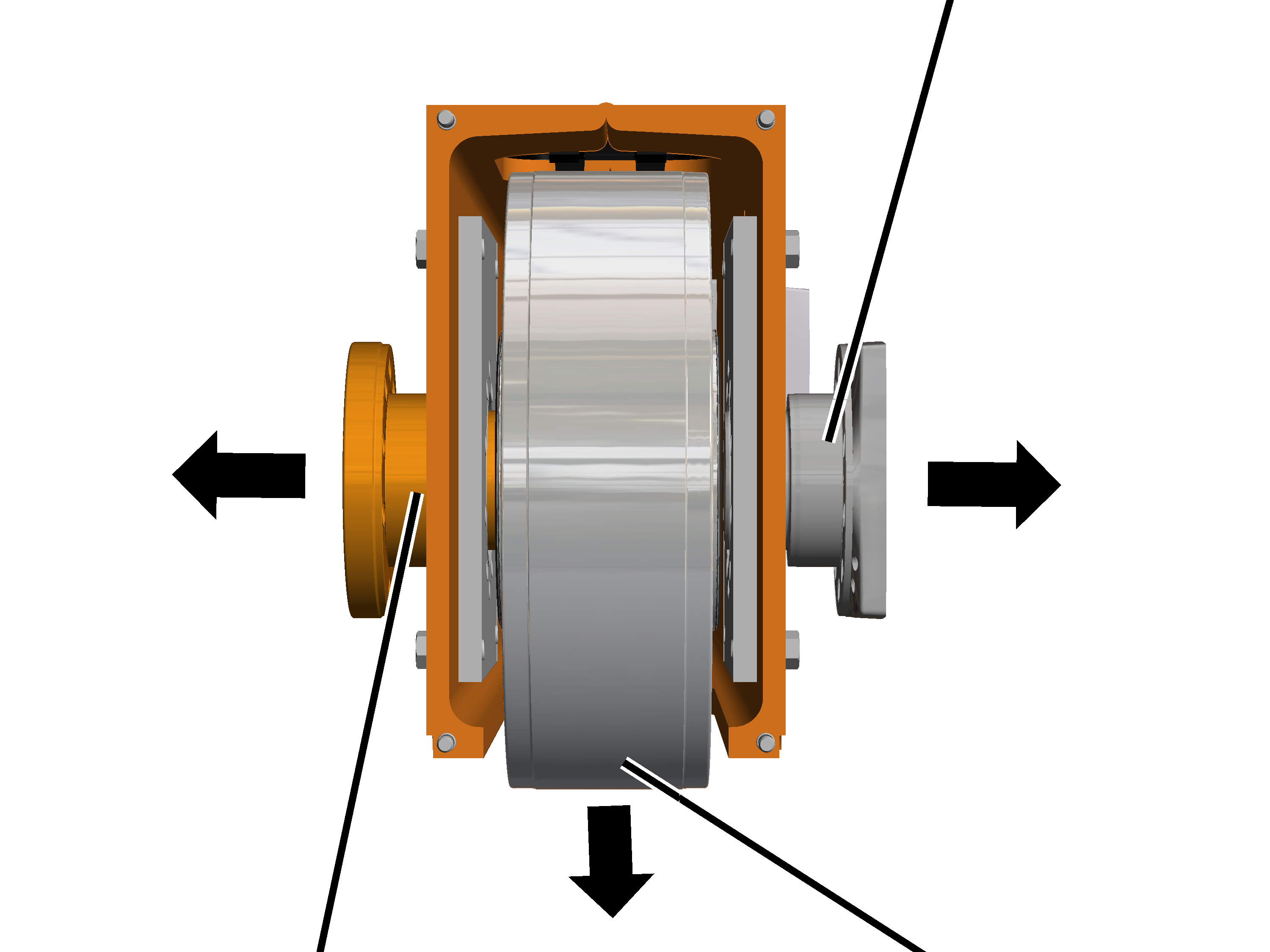
|
Bearing bolt | |
|
|
Bearing flange |
|
| |
|
Bearing bolt |
Wheel |
Take
out the bearing bolt, bearing flange and wheel.
Note:
Only for size 420 with crane travel drive 420 V: An adapter is also inserted on the bearing flange. If this cannot be easily taken off, it can remain on the bearing flange when the wheel is removed.
Tip:
To be able to easily remove the bearing flange from the end carriage, screw two or four screws in the corners of the bearing flange and thereby lift the bearing flange off the end carriage.