|
|
|
|
Dimensions GM 800:
|
Hook path |
Reeving |
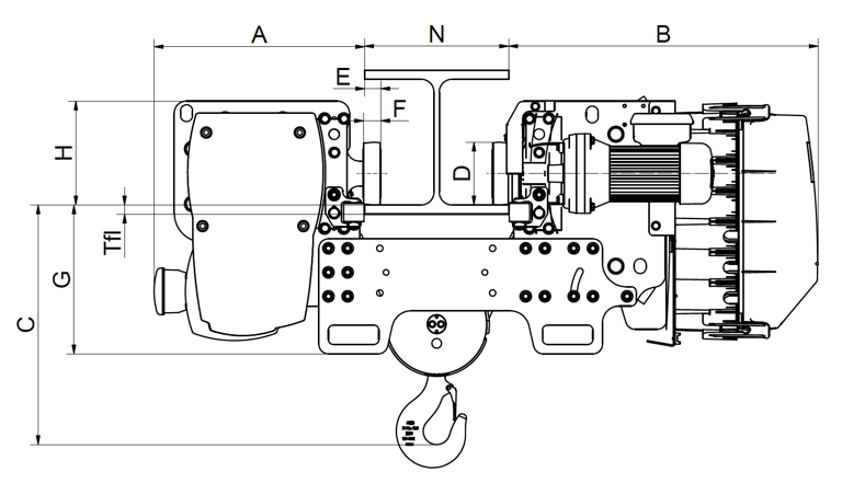
Length (A) |
Length (B) |
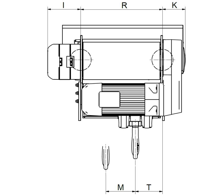
Width (I + R + K) |
Wheel base (R) |
Hook headroom (C) |
Hook headroom enlargement |
|
6 |
4/1 |
416 |
646 |
720 |
438 |
427 |
45 |
|
9 |
4/1 |
416 |
646 |
872 |
590 |
427 |
45 |
|
12 |
2/1 |
416 |
646 |
720 |
438 |
540 |
40 |
|
18 |
2/1 |
416 |
646 |
872 |
590 |
540 |
40 |
The specified hook headroom (C) relates to a flange width
(N) of 300 mm.
For a deviating flange width: Each 50 mm of
additional flange width enlarges the hook headroom (C) by the amount of the
given increase.
Dimensions GM 1000:
|
Hook path |
Reeving |
Length (A) |
Length (B) |
Width (I + R + K) |
Wheel base (R) |
Hook headroom (C) |
Hook headroom enlargement |
|
6 |
4/1 |
438 |
645 |
789 |
507 |
500 |
45 |
|
9 |
4/1 |
438 |
645 |
959 |
677 |
500 |
45 |
|
12 |
2/1 |
438 |
645 |
789 |
507 |
567 |
40 |
|
18 |
2/1 |
438 |
645 |
959 |
677 |
567 |
40 |
The specified hook headroom (C) relates to a flange width of
300 mm.
For a deviating flange width: Each 50 mm of additional
flange width enlarges the hook headroom (C) by the amount of the given
increase.
Weights:
|
Hook path [m] |
Reeving |
GM 800 |
GM 1000 |
|
6 |
4/1 |
266 |
335 – 343 |
|
9 |
4/1 |
289 |
360 – 368 |
|
12 |
2/1 |
256 |
328 – 336 |
|
18 |
2/1 |
278 |
353 – 361 |
The weight of the standard version depends on the design of the hoist motor.
Load specifications:
The load specifications for the wire rope hoist can be obtained from ABUS as a data sheet if necessary. See ABUS Service.
Electrical data for four-pole GM 800 hoist drive with frequency converter.
|
Hoist motor design |
Power output [kW] |
Duty cycle [%] |
Switching rate [c/h] |
Rated current [A] |
cos phi |
|
H |
4.9 |
60 |
360 |
13.5 |
0.97 |
|
H |
4 |
60 |
360 |
10.8 |
0.97 |
|
H |
3.2 |
60 |
360 |
8.6 |
0.97 |
|
H |
2.5 |
60 |
420 |
6.9 |
0.97 |
|
H |
2.0 |
60 |
420 |
5.5 |
0.97 |
Electrical data for four-pole GM 1000 hoist drive with frequency converter.
|
Hoist motor design |
Power output [kW] |
Duty cycle [%] |
Switching rate [c/h] |
Rated current [A] |
cos phi |
|
H |
4.9 |
60 |
360 |
13.5 |
0.97 |
|
H |
4 |
60 |
420 |
10.8 |
0.97 |
|
H |
3.2 |
60 |
420 |
8.6 |
0.97 |
|
H |
2.5 |
60 |
420 |
6.9 |
0.97 |
For electrical data of pole-switchable hoist drives, see separate “Technical data” document of the corresponding hoist drive.
Electrical data for drive with frequency converter:
|
Power output [kW] |
Duty cycle [%] |
Switching rate [c/h] |
Speed ([rpm] |
Rated current [A] |
Travel speed, max. [m/min] |
cos phi N |
|
0.27 |
60 |
240 |
1550 |
1.6 |
20 |
0.97 |
Ambient conditions for operation:
|
|
|
|
Ambient temperature (for normal operation) |
-10 °C to +40 °C |
|
Ambient temperature (for reduced duty cycle) |
+40 °C to +65 °C |
|
Housing |
IP 55 |
|
Insulation class |
F |
Noise emissions:
|
Size |
Sound pressure level LP, m dB(A) at distance of 4 m |
Sound pressure level LW, m dB(A) |
|
GM 800 |
62 |
82 |
|
GM1000 |
64 |
84 |
Table: Noise emissions based on DIN 45635, Part 61 following the substitution process with an acoustic power source
In the table, the sound pressure level LP is specified for a distance of 4 m from the wire rope hoist. To calculate the sound pressure level LW, the sound pressure level at any distance may be used.