Only for four-pole hoist drive with frequency converter
This section only applies if the wire rope hoist has a four-pole hoist drive with frequency converter.
If the air gap on the hoist drive is wider than permitted, the brake rotor must be replaced.
The pictures show the procedure on a GM 1000 modular wire rope hoist. The procedure on GM 800 does not differ significantly from this.
Removing fan cover with auxiliary fan
|
Connection cable |
Connector housing |
|
| |
|
Plug-in connection of auxiliary fan |
Housing cover of connector housing |
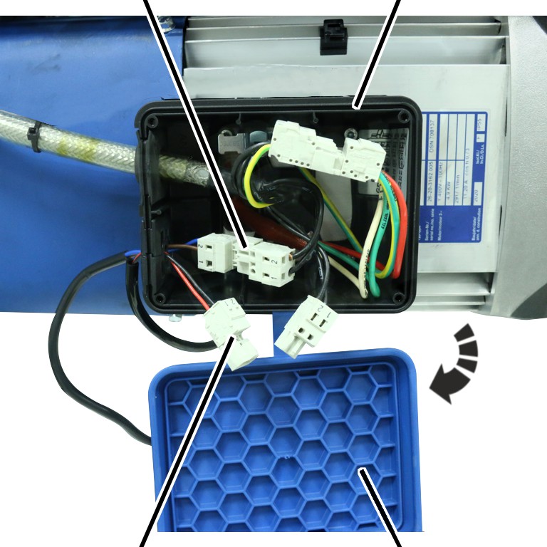
 Open the housing cover of the
connector housing.
Open the housing cover of the
connector housing.
Disconnect the plug-in
connection of the auxiliary fan.
|
|
Connector housing |
|
| |
|
Connection cable of auxiliary fan |
Sectioned cable bushing |
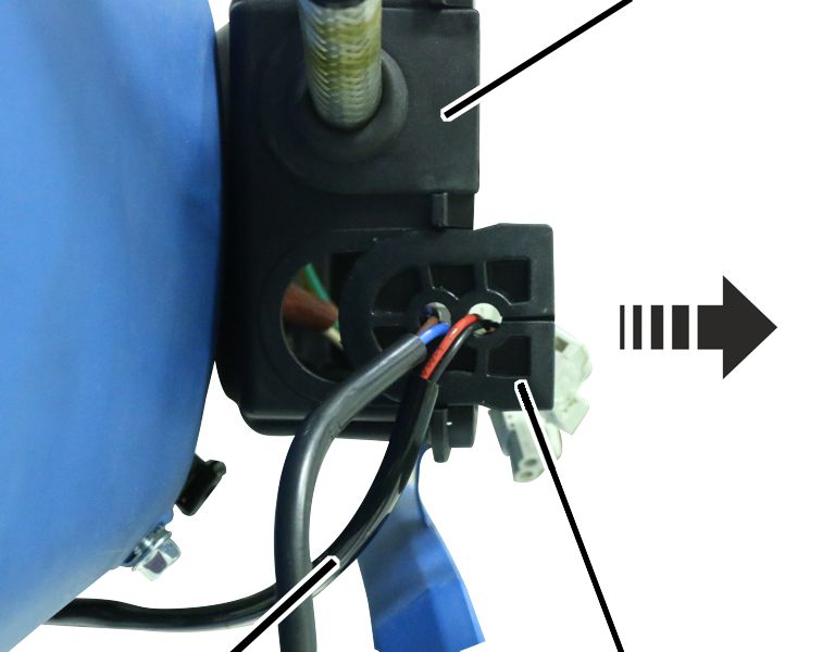
Pull out cable bushing.
Expose connection cable.
Detach cable clips on the cable
fastener.
Disassembling the auxiliary fan
|
|
Auxiliary fan |
|
| |
|
Fillister-head screws M4x12 |
|
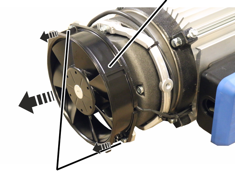
Hold the auxiliary fan and
remove the fillister-head screws M4x12 (2x).
Remove the auxiliary fan and
ensure than it is not suspended from the connection cable.
|
| |
|
Countersunk screws M4x10 |
Mounting |
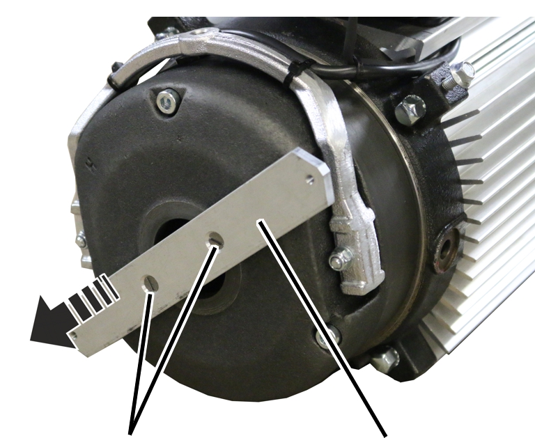
Remove the countersunk screws
M4x10 (2x).
Remove the mounting.
Disassembling the magnet body
|
Fillister-head screws |
Magnet body |
|
| |
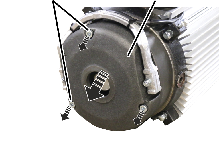
Remove the fillister-head screws
M6x60 (3x).
Take off the magnet body.
Replacing the brake rotor
|
Brake rotor with brake lining |
|
|
| |
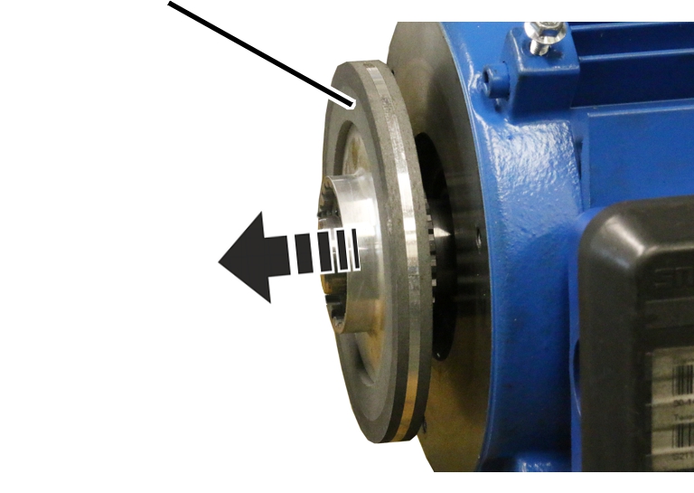
Pull the brake rotor from the
hub.
Put new brake rotor onto the
hub.
Installing the brake and auxiliary fan
Place the magnet body on the
motor shaft.
Tighten the magnet body with
fillister head screws M6x60 (3x). 9 Nm.
Screw on the mounting using
countersunk screws M4x10 (2x) until hand-tight.
Screw the auxiliary fan onto the
mounting using fillister-head screws M4x12 (2x).
Attach the fan cover and screw
it in place.