Pull the fan cover off to the rear.
The brake lining thickness must be measured to check the brake. The brake must be disassembled to do so.
The pictures show the procedure on a GM 1000 modular wire rope hoist. The procedure on GM 800 does not differ significantly from this.
Overview:
|
Dimension |
Value |
|
Brake lining thickness, new |
6.05 mm |
|
Brake lining thickness, minimum |
5.8 mm |
If the brake lining on the drive is thinner than permitted, then the brake rotor must be replaced.
If the thickness of the brake lining is within the permitted range, but usage behaviour leads to the expectation that the brake lining thickness will be thinner than permitted before the next regular inspection, the brake lining must be replaced now.
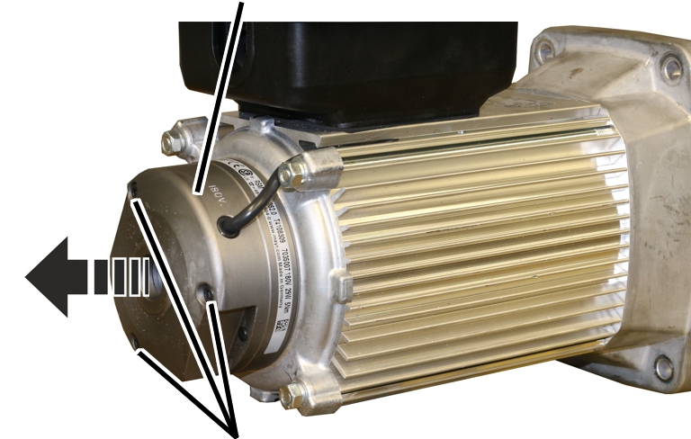
Pull the fan cover off to the rear.
|
Magnet body |
|
|
| |
|
Fillister-head screws |
|
 Unscrew the fillister-head screws (3x).
Pull the magnet body off the drive from the rear.
|
|
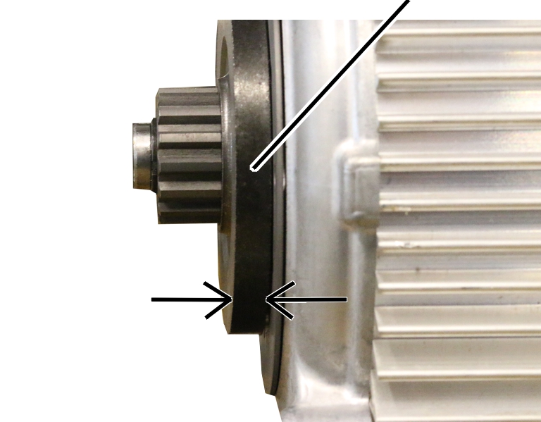
Brake rotor with brake lining |
|
| |
Measure the brake lining thickness.
If the brake lining thickness is less than 5.8 mm: Replace the
brake rotor. See Replacing the brake rotor on the
drive.
The air gap on the brake cannot be adjusted or readjusted.
|
|
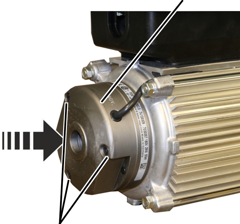
Magnet body |
|
| |
|
Fillister-head screws |
|
Insert magnet body.
Tighten the magnet body with fillister head screws M4x45 (3x).
2.5 Nm.
Attach the fan cover.