Only for four-pole hoist drive with frequency converter
The pictures show the procedure on a GM 1000 modular wire rope hoist. The procedure on GM 800 does not differ significantly from this.
Connecting the hoist motor
|
Cable bushing |
Screening clamp connection |
|
| |
|
Connection cable |
Plug-in connection |
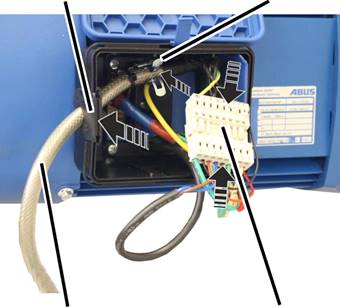
 Open the housing cover.
Insert the bush multipoint connector for the drive on the pin
multipoint connector on the drive.
Insert the bush multipoint connector for the brake on the pin
multipoint connector on the drive.
 Push the front end of the connection cable (where the sheathing
around the shield has been removed) into the screening clamp connection.
Push the front end of the connection cable (where the sheathing
around the shield has been removed) into the screening clamp connection.
Fasten the connection cable to the screening clamp connection using
cable ties.
Lay the plug-in connections and connection cable in the connector
housing.
Close the housing cover.
Connecting wires to the plug-in connection
|
Protective conductor |
Auxiliary fan |
|
| |
|
Winding of the hoist motor |
Brake |
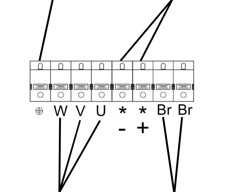
Connect the lead end of the protective conductor onto the terminal
with the protection conductor symbol.
Observe the polarity and connect the auxiliary fan to the terminals
with the fan symbol.
Connect the brake to the “Br” terminals.
Connect the winding of the motor to the terminals W, V and U.