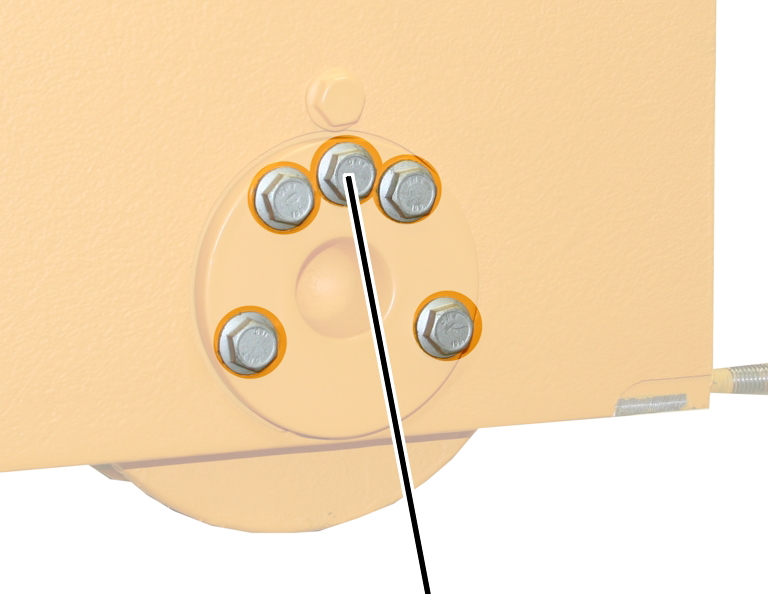
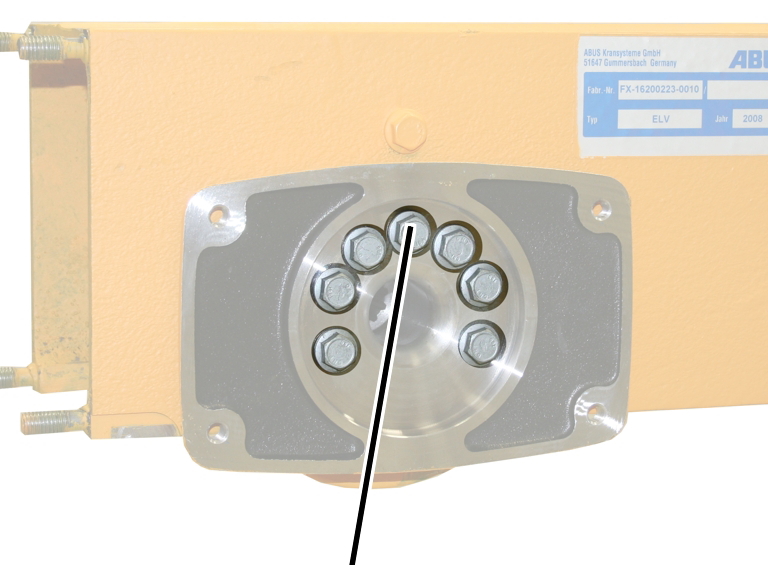
Bearing bolt
Bearing flange
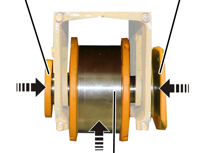
Wheel
If the wheel is damaged or worn, it must be replaced by a new wheel.
The figures show the assembly of a size 130 wheel. The mounting of larger wheels does not essentially differ from this.
|
Bearing bolt |
Bearing flange |
|
| |
|
Wheel | |
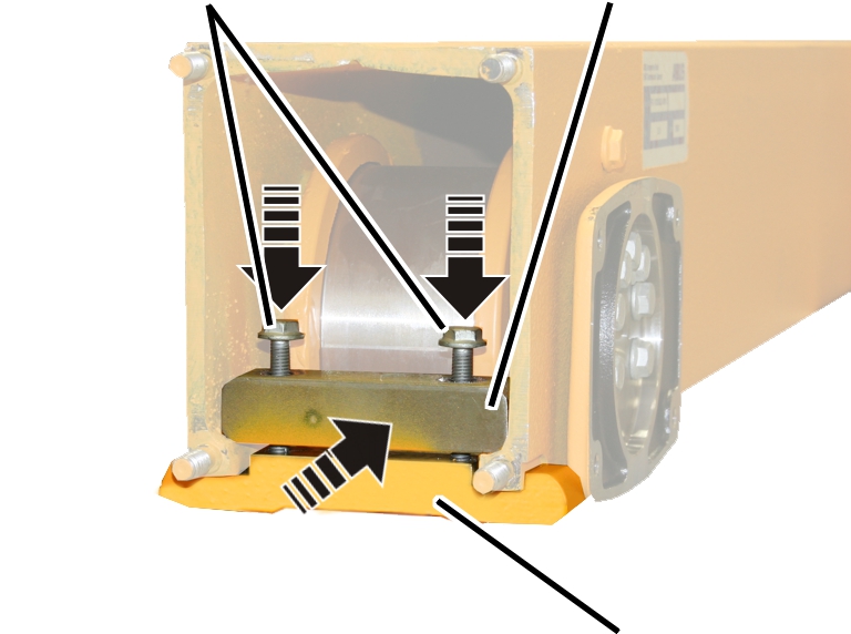
 Clamp
the wheel in the end carriage. It does not matter which side faces inwards or
outwards.
Clamp
the wheel in the end carriage. It does not matter which side faces inwards or
outwards.
Insert the bearing bolt and
bearing flange. If necessary, lightly hammer the bearing bolt and bearing
flange.
|
|
|
Rib screws |
Tighten the rib screws in stages.
|
Wheel Ø |
Strength category |
Number |
Screw |
Tightening torque |
|
130 |
10.9 |
5x |
M8x25 |
42 Nm |
|
160 |
10.9 |
5x |
M8x25 |
42 Nm |
|
200 |
10.9 |
5x |
M10x30 |
85 Nm |
|
280 |
10.9 |
5x |
M12x40 |
130 Nm |
|
350 |
10.9 |
8x |
M12x40 |
130 Nm |
|
420 |
10.9 |
8x |
M16x40 |
330 Nm |
This work step only applies if an end carriage size 420 is to be installed with a crane travel drive size 420 V.
|
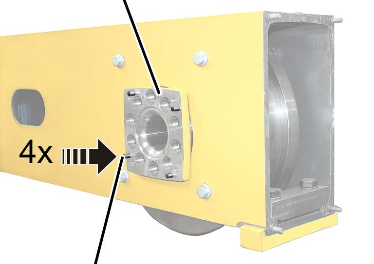
Bearing flange |
| |
|
| ||
|
Pin |
| |
If
necessary: Insert the pins (4x) in the bearing flange.
|
| |
|
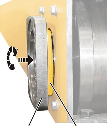
Adapter |
Bearing flange |
Turn
the adapter to match the hole pattern.
Place the adapter on the pins on
the bearing flange.
|
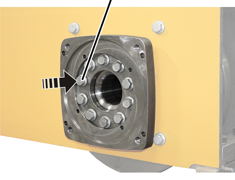
Rib screws |
|
|
Insert the rib screws M16x70 (10x) through the adapter
and bearing flange.
|
|
|
Rib screws |
Tighten the rib screws in stages.
|
Wheel Ø |
Strength category |
Number |
Type |
Tightening torque |
|
130 |
10.9 |
7x |
M8x25 |
42 Nm |
|
160 |
10.9 |
7x |
M8x25 |
42 Nm |
|
200 |
10.9 |
7x |
M10x30 |
85 Nm |
|
280 |
10.9 |
7x |
M12x40 |
130 Nm |
|
350 |
10.9 |
10x |
M12x40 |
130 Nm |
|
420 with crane travel drive 420 |
10.9 |
10x |
M16x40 |
330 Nm |
|
420 with crane travel drive 420 V |
10.9 |
10x |
M16x70 |
330 Nm |
This work step applies only to end carriages of the sizes 280, 350 and 420.
|
Screws |
Clamping element | |
|
| ||
|
|
Clamping piece | |
Tighten screws (2x).
|
Wheel Ø |
Type |
Kind |
Tightening torque |
|
130 |
M8x45 |
Rib screw |
42 Nm |
|
160 |
M10x50 |
Rib screw |
85 Nm |
|
200 |
M10x50 |
Rib screw |
85 Nm |
|
280 |
M12x60 |
Hexagon head screw |
130 Nm |
|
350 |
M20x75 |
Hexagon head screw |
300 Nm |
|
420 |
M20x75 |
Hexagon head screw |
300 Nm |
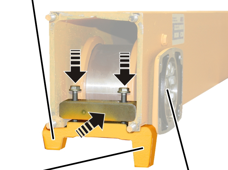
This work step only applies if the end carriage has guide rollers.
|
Screws |
Clamping element | |
|
| ||
|
Bracket |
Guide rollers | |
Insert bracket with guide
rollers.
Tighten screws (2x).
|
Wheel Ø |
Type |
Kind |
Tightening torque |
|
130 |
M8x45 |
Rib screw |
42 Nm |
|
160 |
M10x50 |
Rib screw |
85 Nm |
|
200 |
M10x50 |
Rib screw |
85 Nm |
|
280 |
M12x60 |
Hexagon head screw |
130 Nm |
|
350 |
M20x75 |
Hexagon head screw |
300 Nm |
|
420 |
M20x75 |
Hexagon head screw |
300 Nm |
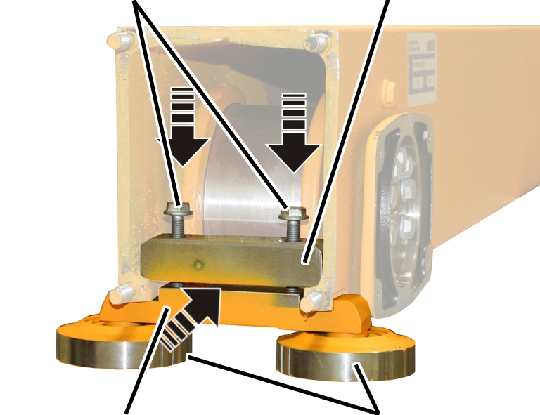
This work step only applies if the end carriage has a derailing protection device.
|
Small side | |
|
| |
|
Large side |
Crane travel drive |
Insert the derailing protection
device.
Tighten screws (2x).
|
Wheel Ø |
Type |
Kind |
Tightening torque |
|
130 |
M8x45 |
Rib screw |
42 Nm |
|
160 |
M10x50 |
Rib screw |
85 Nm |
|
200 |
M10x50 |
Rib screw |
85 Nm |
|
M12x60 |
Hexagon head screw |
130 Nm | |
|
350 |
M20x75 |
Hexagon head screw |
300 Nm |
|
420 |
M20x75 |
Hexagon head screw |
300 Nm |
|
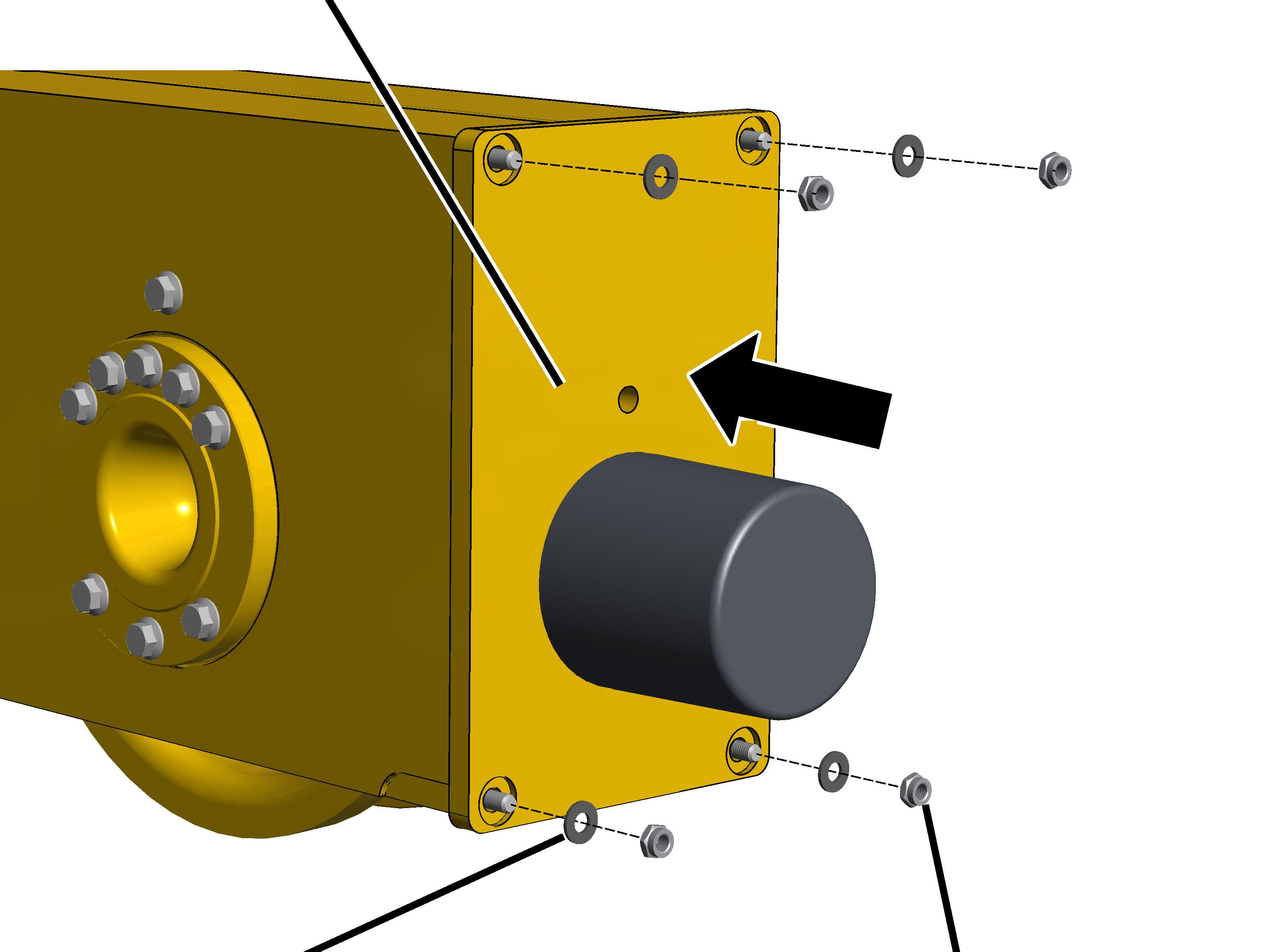
Buffer plate |
|
|
| |
|
Plastic washer |
Self-locking nut |
Slide the buffer plate onto the threaded
bolt.
From size 160: fit the plastic
washers (4x) in place.
Tightly screw the self-locking
nuts M10 (4x). 6 Nm.
The self-locking nuts may only be reused maximally 3 times. After this, new self-locking nuts must be used.
Determine
the weight of the drive. See the ABUS Drive product manual.
|
|
Bearing flange |
|
| |
|
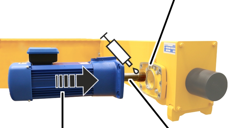
Drive |
Output shaft |
Lubricate the gearing on the output shaft. Apply
lubricant with brush to coat surface completely.
Lubricant: “High temperature paste PBC 1574”. See the ABUS Drive product manual for details.
Push the drive into the wheel.
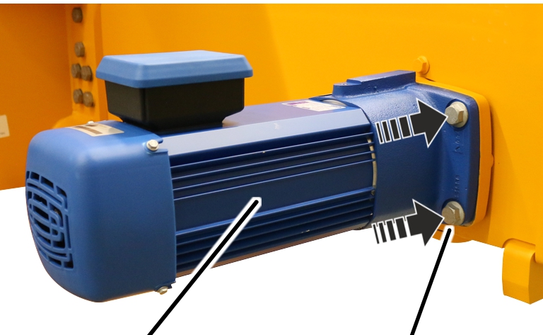
This work step only applies when an AZP drive is to be mounted on the end carriage.
|
| |
|
AZP drive |
Rib screw |
Bolt on the drive with the rib
screws (4x).
|
Size |
Type |
Tightening torque |
|
130 |
M8x25 |
35 Nm |
|
160 |
M10x30 |
75 Nm |
|
200 |
M12x30 |
115 Nm |
|
280 |
M16x40 |
300 Nm |
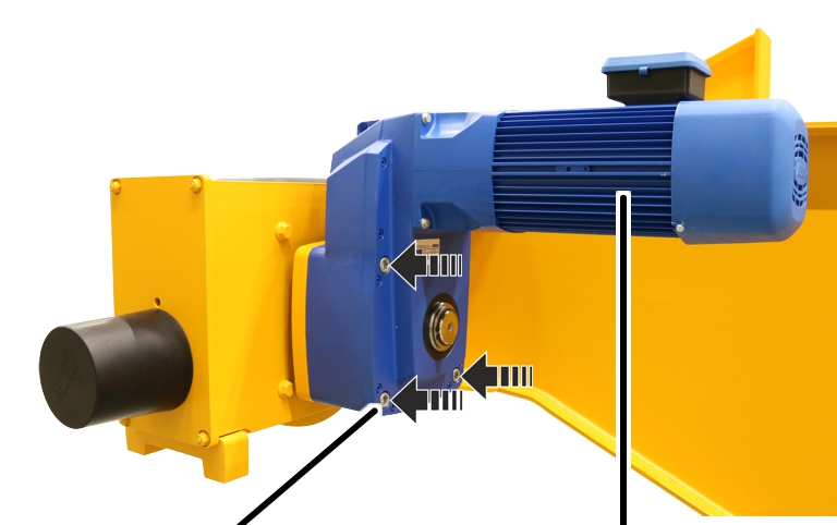
This work step only applies if an AZF crane travel drive is to be mounted on the end carriage.
|
| |
|
Fillister-head screw |
Crane travel drive AZF |
Insert the crane travel drive in the wheel.
Bolt on the crane travel drive
with the fillister-head screws and washers (4x).
|
Size |
Type |
Tightening torque |
|
350 |
M12x100 |
85 Nm |
|
420 |
M12x100 |
85 Nm |
|
V420 |
M16x140 |
210 Nm |
|
V500 |
M16x140 |
210 Nm |
|
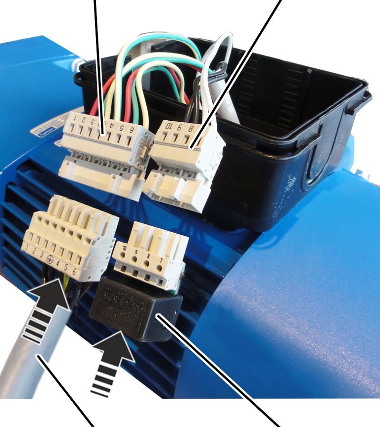
Pin
multipoint connector |
Pin
multipoint connector |
|
| |
|
Connection cable of drive |
Rectifier for brake |
Insert the connection cable for
the drive in the pin multipoint connector on the drive.
Insert the rectifier for the
brake in the pin multipoint connector on the drive.
Lay the plug-in connections and
connection cable in the connector housing.
|
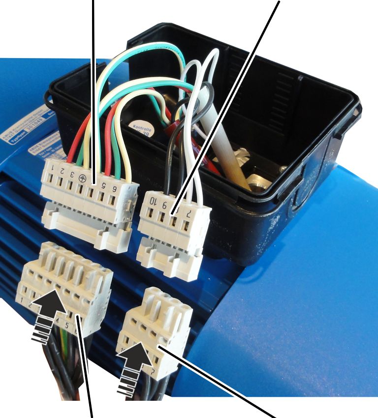
Pin
multipoint connector |
Pin
multipoint connector |
|
| |
|
Bush
multipoint connector |
Bush multipoint connector |
Insert the bush multipoint
connector for the drive on the pin multipoint connector on the drive.
Insert the bush multipoint
connector for the brake on the pin multipoint connector on the drive.
|
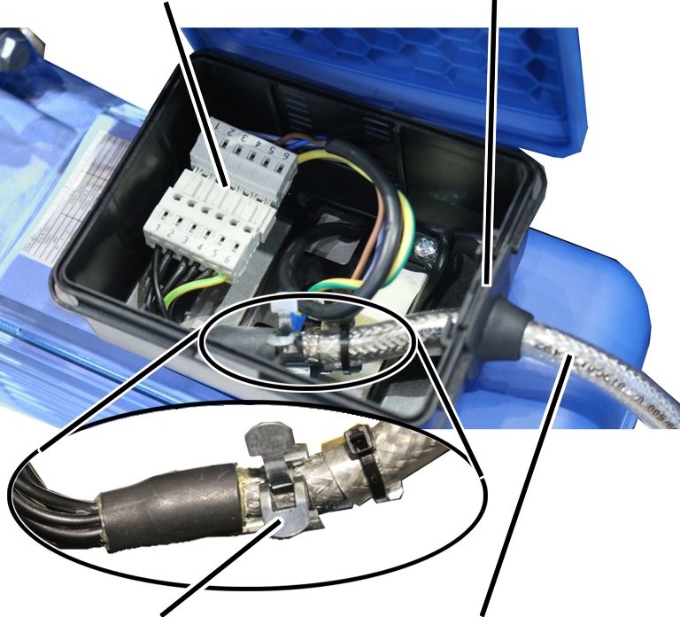
Plug-in connection |
Cable bushing |
|
| |
|
Screening clamp connection |
Connection cable |
Push the front end of the
connection cable (where the sheathing around the shield has been removed) into
the screening clamp connection.
Fasten the connection cable to
the screening clamp connection using cable ties.
Lay the plug-in connections and
connection cable in the connector housing.
Close the housing cover.
Replace the crane on the crane
track.
Put the crane into
operation.
Inspect the function of the
wheel.