The following requirements must be met in order for the semi-goliath crane to be assembled.
─ The tolerances of the crane track must correspond to the following criteria.
The tolerances specified correspond to DIN 4132 and the VDI guideline 3576 for crane classifications B1 to B3.
Position of upper crane track in floor plan B:
|
|
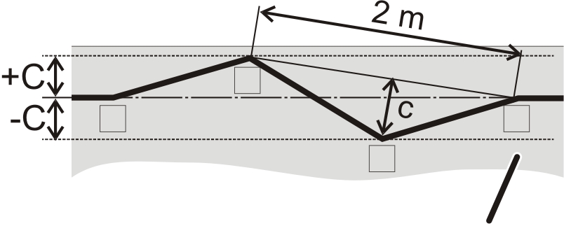
View from above.
─ Deviation B across the entire length of the crane track: B = ± 10 mm.
─ Within 2 m, the deviation may not be greater than b = ± 0.5 mm.
Height of upper crane track C:
|
| |
|
|
Wall (view from the side) |
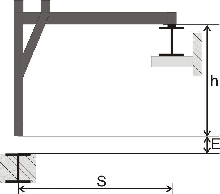
View from the side.
─ Deviation C across the entire length of the crane track: C = ± 10 mm.
─ Within 2 m, the deviation may also not be greater than C = ± 2 mm.
Height of the crane tracks in relation to each other E:
|
|
Cross-sectional view.
─ The height of the crane (lower edge of wheel on upper and lower end carriage) is subtracted.
─ The height difference between the crane tracks E (in mm) may not be larger than E = ± 1.0 x span S (in m; do not calculate in millimetres but instead replace the unit m with mm; height of crane is subtracted).
─ Maximum height difference E = ± 10 mm.
Incline of the crane tracks to each other Δhr:
|
|
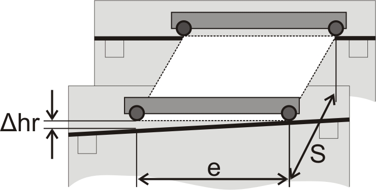
View from the side (perspectively)
─ The
incline of the crane tracks toward each other Δhr (in mm) may not be
larger than Δhr = ± 1.0 x span S or
as
Δhr = ± 0.1 x wheelbase e
(S and e in m;
do not calculate in millimetres but instead replace the unit m with mm; height
of crane is subtracted)
─ The smaller of the two calculated Δhr-values are considered the maximum incline of the crane tracks.
─ Maximum incline of the crane tracks to each other: Δhr = ± 10 mm.
Incline of the crane track from the horizontal vertex G:
|
|
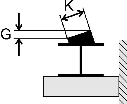
Cross-sectional view.
─ Deviation G = 0.6% of the width K.
─ The supplied overhead travelling crane must correspond to the overhead travelling crane that was provided for in the layout plan.
─ The order of the overhead travelling cranes on the crane track must be decided.
This section only applies to wheels of the lower end carriage which run directly on the building floor and are plastic-coated.
─ The building floor must be adequate for the expected loads of the semi-goliath crane and consequently have the appropriate load-bearing capacity.
─ The building floor must be single-layered and contain no other layers (screed, tiles, etc.), i.e. the building floor must be level, even and without interfering edges. The coefficient of friction must not exceed a value of my = 0.45. If necessary, an appropriate coating must be permanently applied to the area of the crane track.
This section only applies to wheels of the lower end carriage which run on a crane track in the building floor.
|
Upper edge of crane track |
|
|
| |
─ As crane track, an I-beam should be used.
─ The surface of the crane track may not be painted, galvanised or otherwise coated.
─ The crane track must be flush with the building floor.
─ The crane track must have a width of at least 260 mm.
Incline of the lower crane track from the horizontal vertex G:
|
|
Cross-sectional view.
─ Deviation G = 0.8% of the width K.