The figures show the installation of a VKL conductor system on a steel HB profile rail of size HB150S. The installation on larger or smaller HB profile rails or aluminium HB profile rails does not differ significantly from this.
|
|
The figures show the installation of a VKL conductor system on a steel HB profile rail of size HB150S. The installation on larger or smaller HB profile rails or aluminium HB profile rails does not differ significantly from this. |
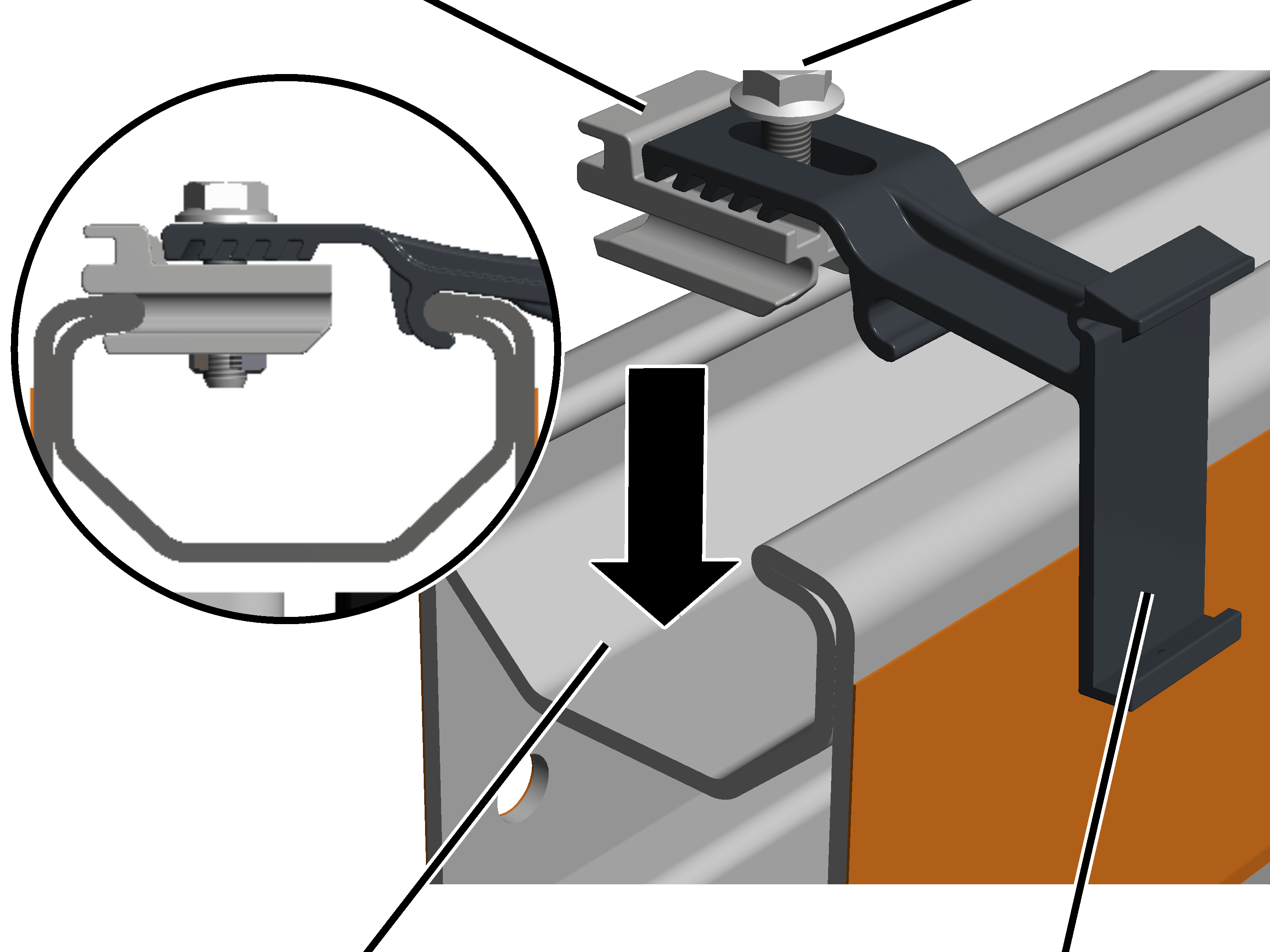
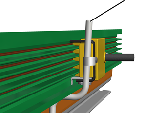
The conductor system VKL is installed on the profile head of the HB profile rail with brackets.
|
|
Where and at what intervals the brackets are mounted is specified in the planning documents. |
On each support:
|
Clamping element |
Rib screw M8x30 |
|
| |
|
Profile head |
Rail retainer |
 Turn the clamping element
as shown in the diagram.
Turn the clamping element
as shown in the diagram.
Insert the bracket in the
profile head from above.
Screw the M8x30 rib screw
tight.
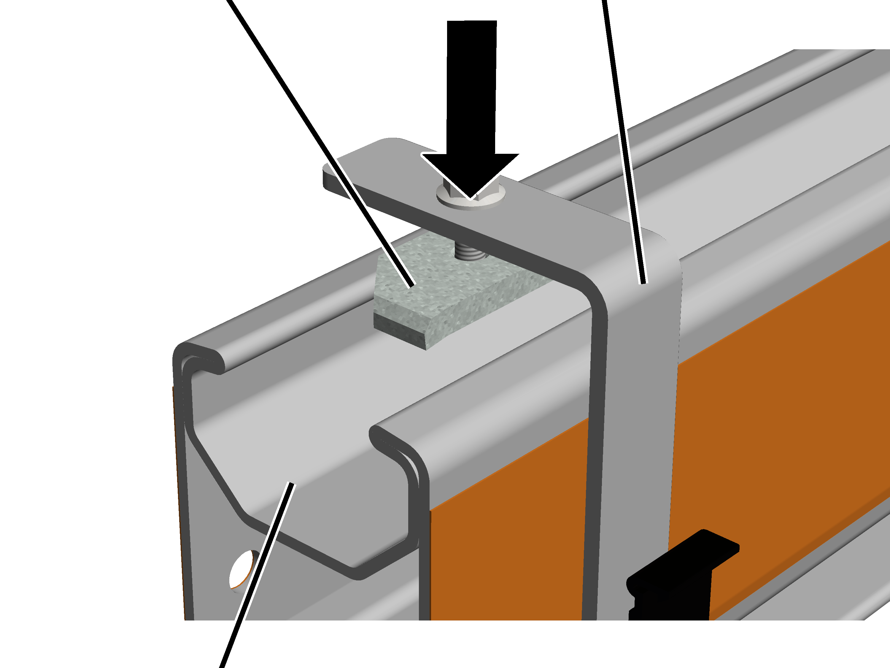
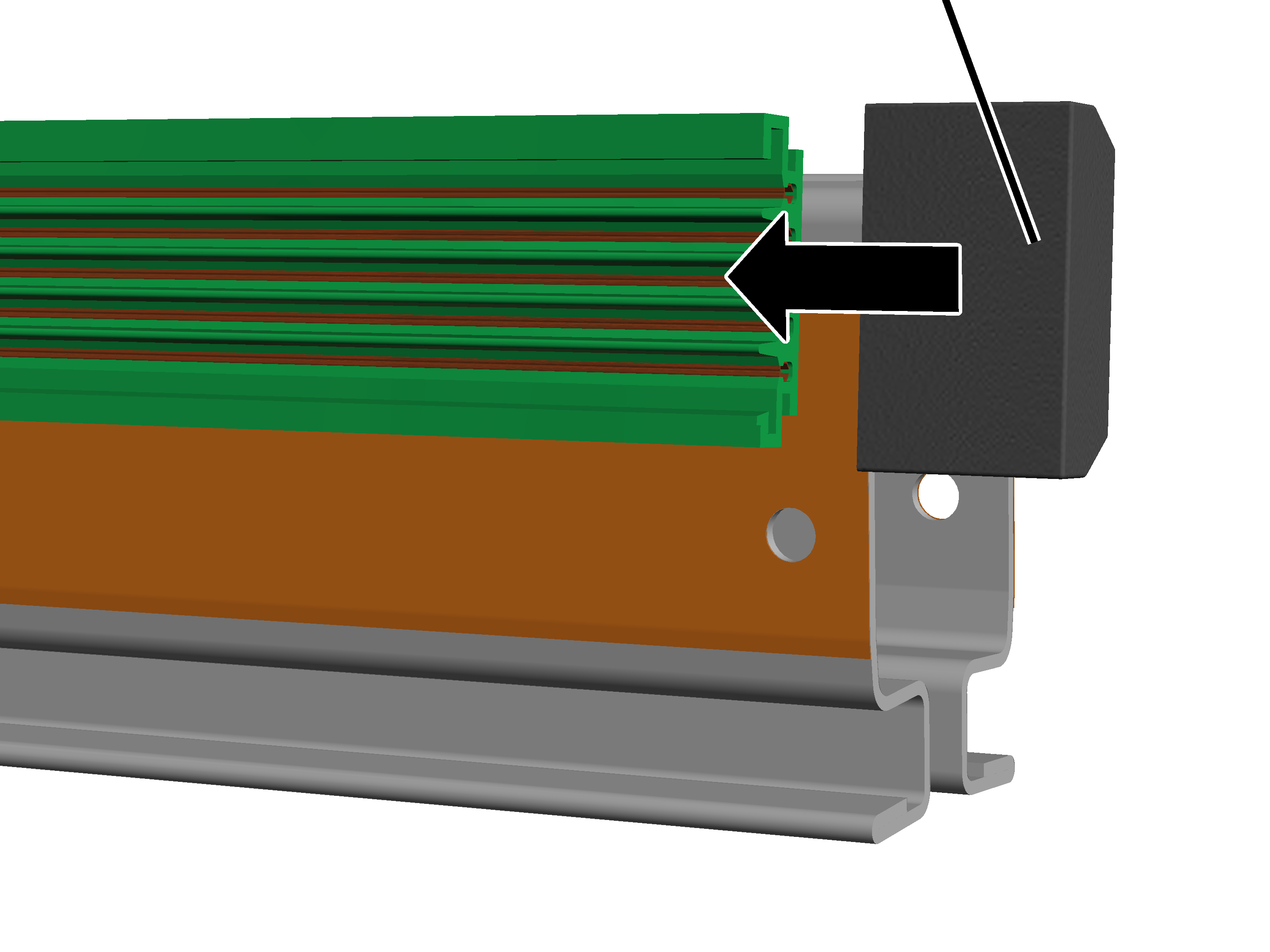
This section only applies to a VKL conductor system on the crane girder.
On each support:
|
Head nut |
Support |
|
| |
|
Profile head |
|
Turn the head nut in the
longitudinal direction and lay the support on the profile head from above.
● The head nut extends into the profile head.
Tighten the rib screws.
25 Nm.
● The head nut turns during fixing in the crosswise direction and is clamped tight in the profile head.
Lay out the individual
sections of the conductor system on the floor as they will later be installed on
the HB profile rail.
|
|
What position is intended for the power line is specified in the planning documents. |
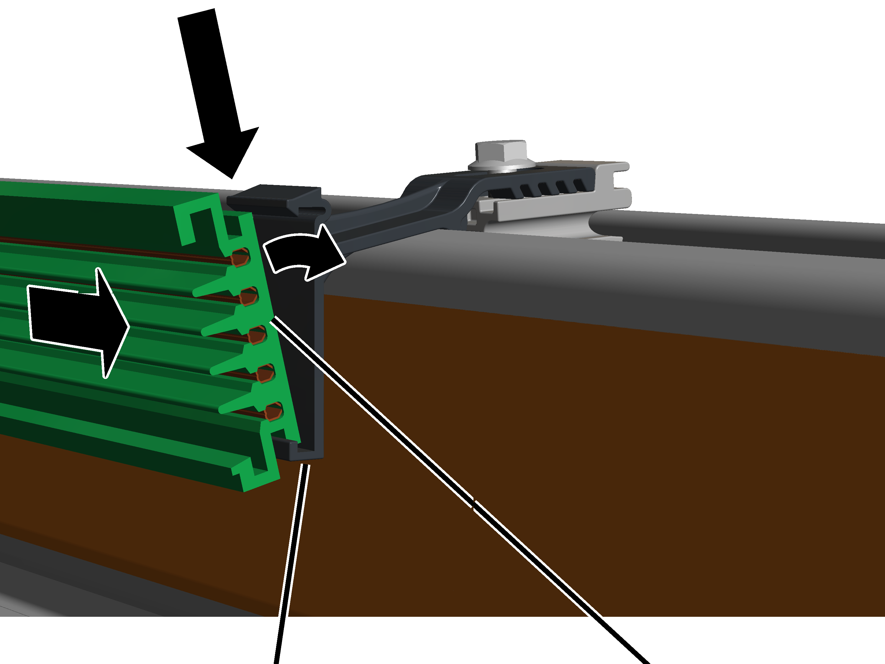
For every section:
|
| |
|
Support |
Section |
Insert the section bottom
in the bracket and latch it at the top.
|
|
What position is intended for the feed unit is specified in the planning documents. |
|
Feed unit |
|
|
| |
|
|
Section |
Install the feed unit at
the location specified in the planning documents.
The feed unit is fixedly installed on a one-metre long section. This is installed as a regular section.
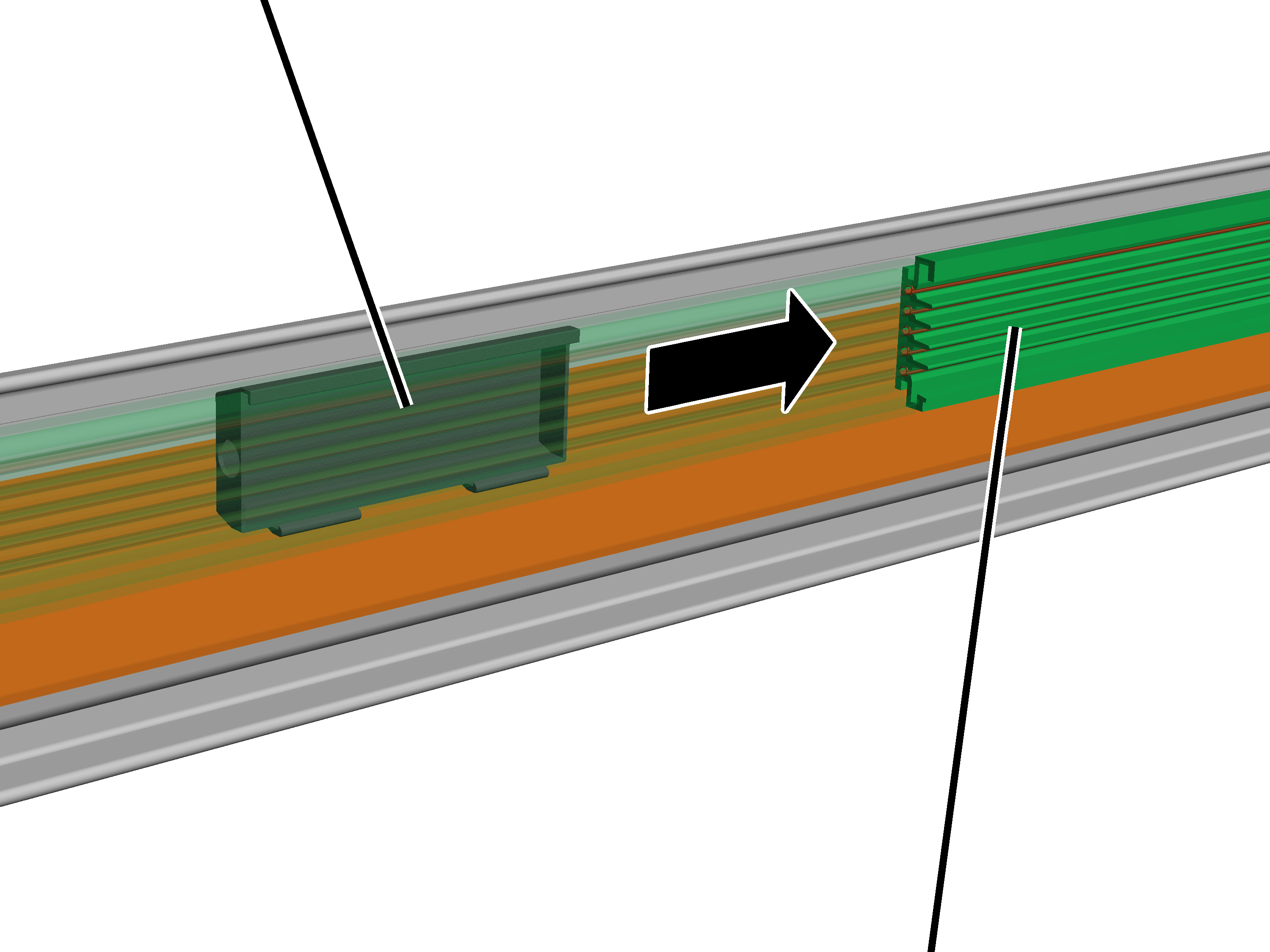
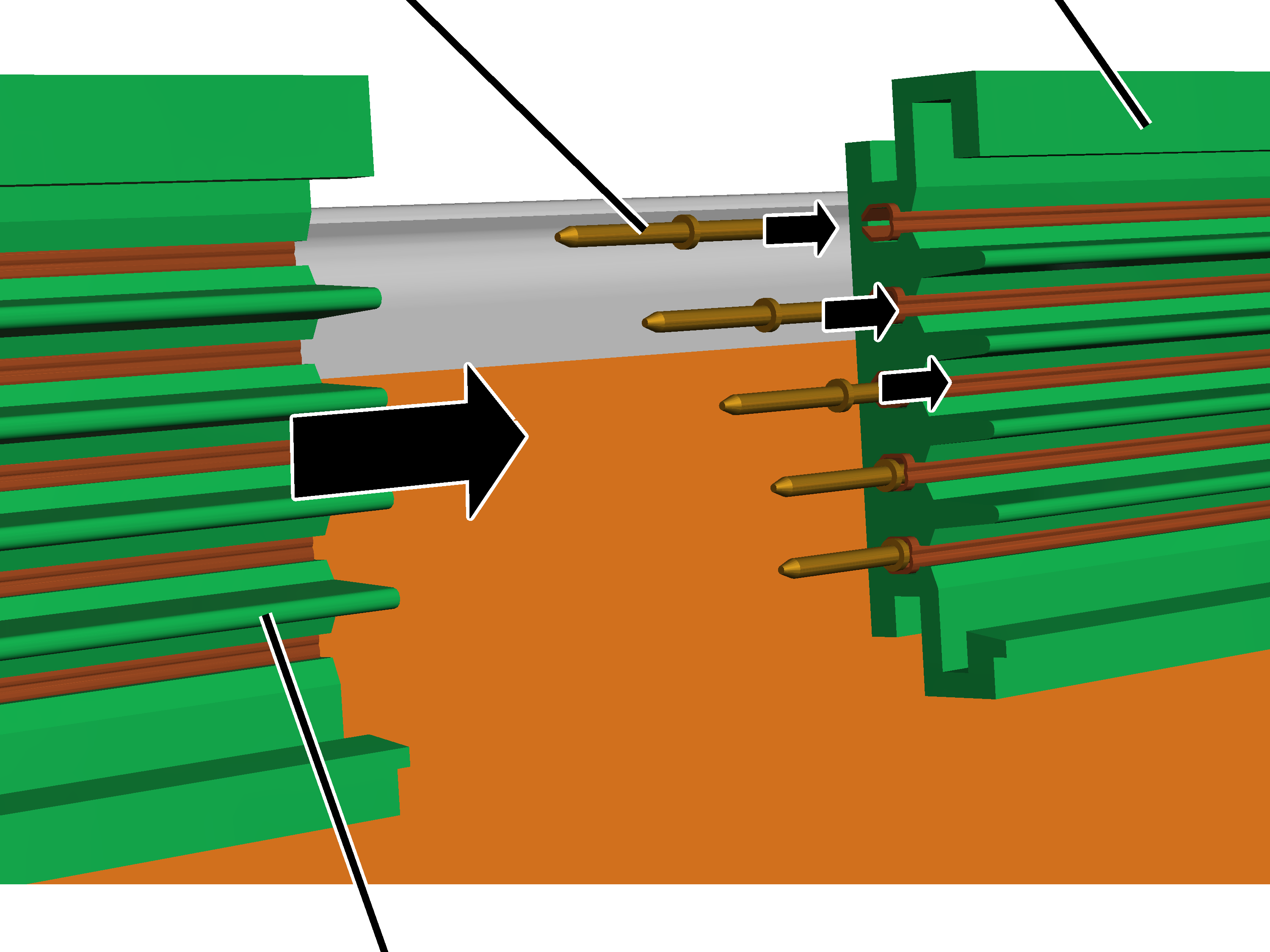
The sections are electrically connected with one another by means of connecting pins.
At every joint:
|
Connecting pins |
Section |
|
| |
|
Section |
|
Insert the connecting pins
laterally in the rails of a section.
Insert the connecting pins in the rails preferably at varying depths. This will facilitate the positioning of the next section.
Push the section up to the
previous section.
Insert the connecting pins
of the previous section into the rails of the next section.
Place a wood block at the
end of a section and use hammer to strike the section against the previous
one.
● The connecting pins are inserted fully into the rail and are no longer visible.
Tip:
To prevent the conductor system slipping away during striking, fix the first section to the HB profile rail. To do this push a suitable piece of wood between the conductor system and the HB profile rail, place a second piece of wood on the conductor system and fix in place using a screw clamp.
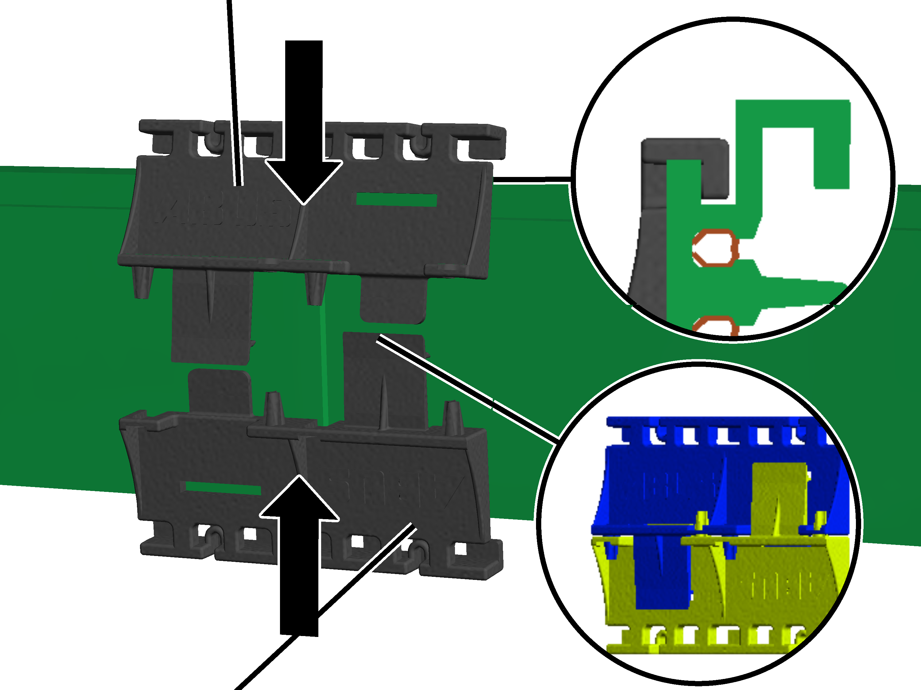
A two-piece connector can also be used to connect the sections with each other mechanically.
At every joint:
|
Connector |
|
|
| |
|
Connector |
|
Push the halves of the
connector onto the conductor system from above and below.
The two halves for top and bottom are identical.
Align the connectors so
that the plastic lugs slip precisely into the undercut on the conductor
system.
Insert the connectors into
one another behind the conductor system.
One of the sections is now fixed to the bracket. The other sections remain loosely latched. This allows the entire conductor system to freely expand or contract when temperatures change. However, due to the one fixedly bolted section, the entire conductor system cannot slide into the brackets.
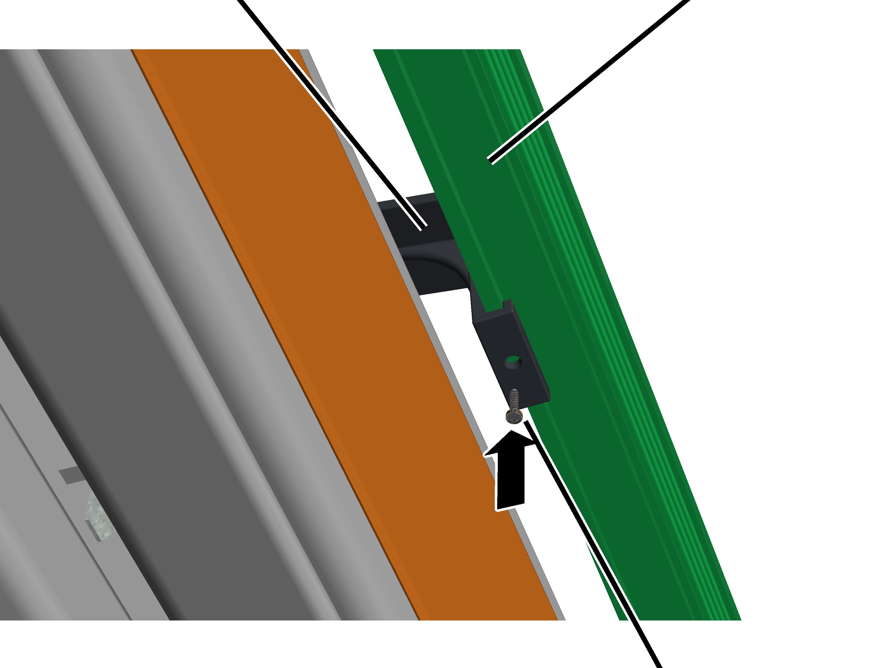
The section to be bolted should lie about in the middle (within the span of the conductor system).
Centred within the span of the conductor system:
|
Support |
Section |
|
| |
|
|
Self-tapping screw |
Screw the self-tapping
screw from below into the bracket and section.
|
| |
|
Current collector |
|
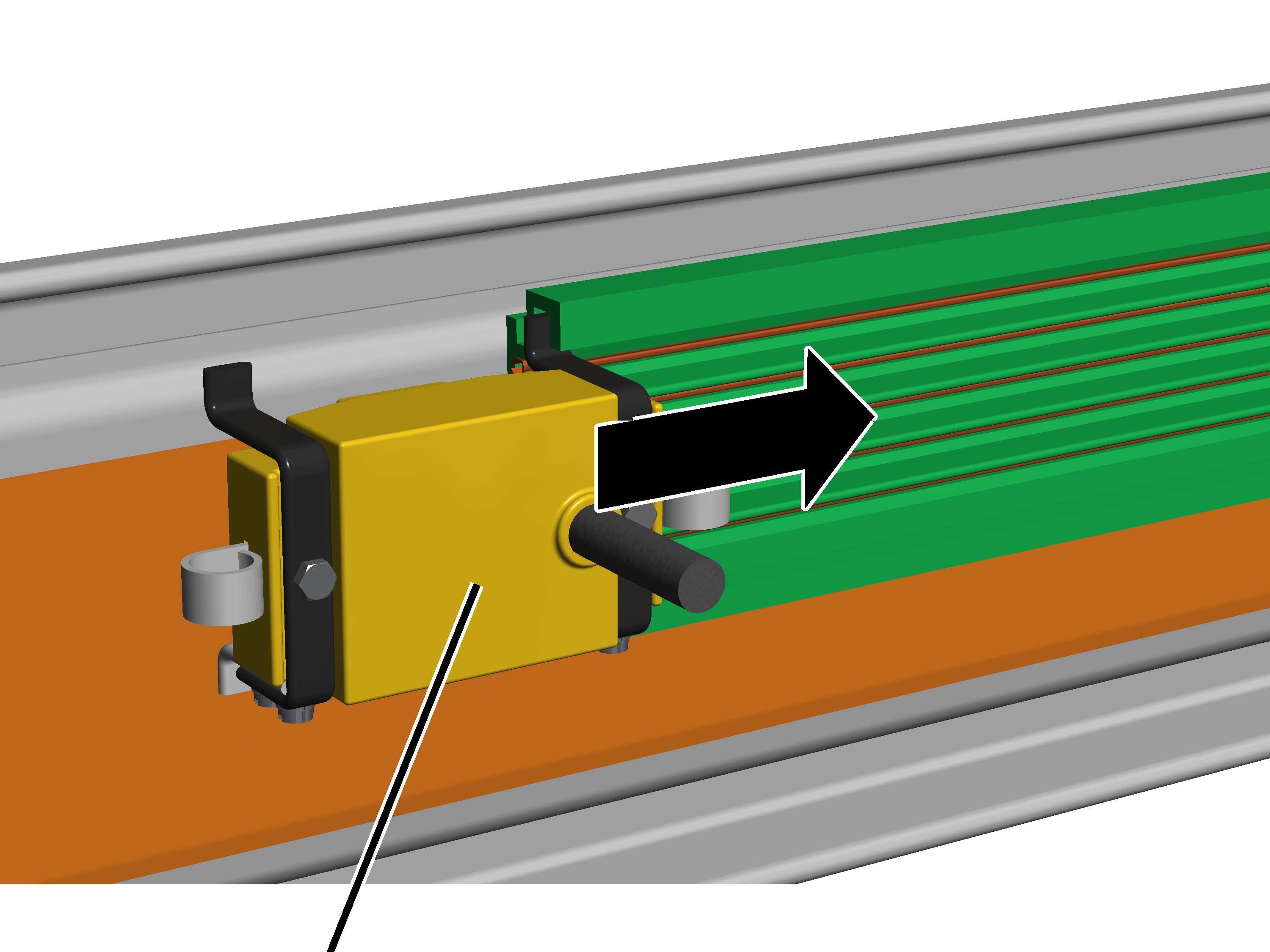
 Slide the current
collector into the conductor system.
Slide the current
collector into the conductor system.
Slide the current
collector over the entire length of the conductor system to test it.
The current collector must move smoothly and not get caught, particularly at the joints.
On the trolley:
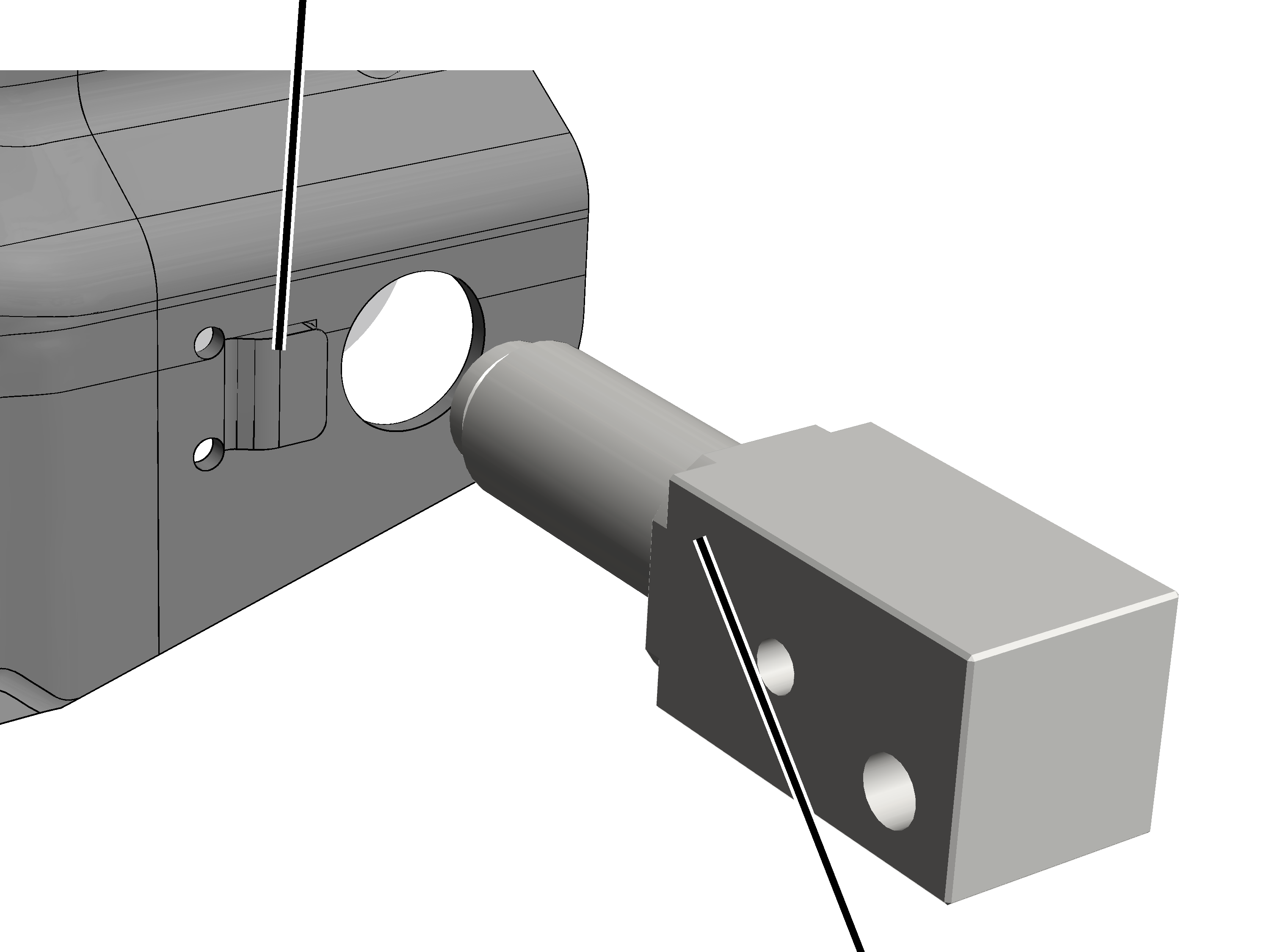
This work step is only applicable if the trolley has a protruding nose next to the drilled hole as an integrated anti-rotation device.
|
Integrated anti-rotation device |
|
|
| |
|
|
Carrier shaft |
Push the carrier shaft
directly into the drilled hole on the trolley.
Do not use the included separate anti-rotation device!
● The carrier shaft is secured on the trolley by means of an integrated anti-rotation device and cannot turn.
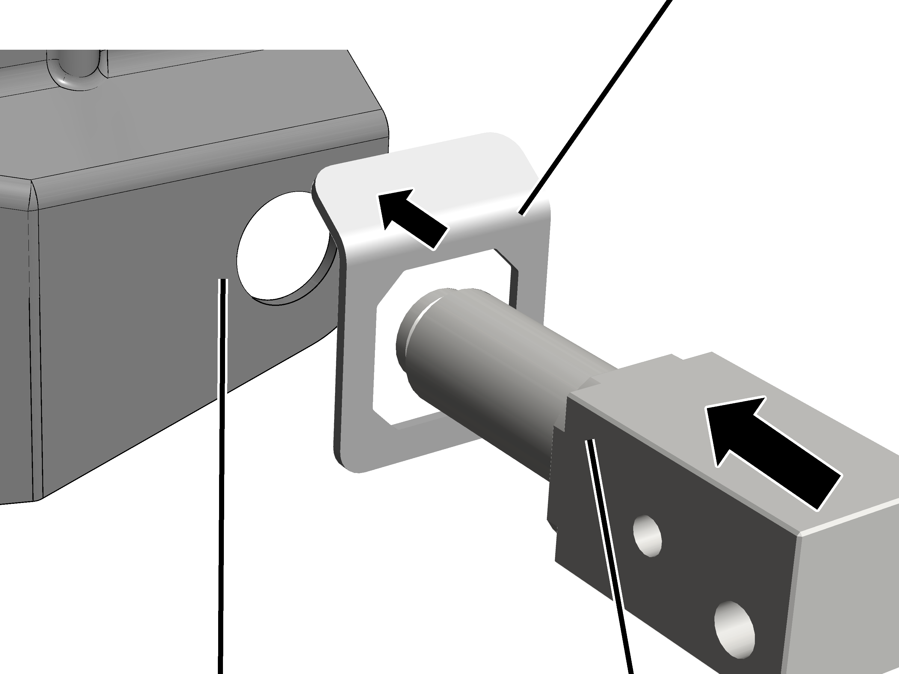
This work step is only applicable if the trolley does not have an integrated anti-rotation device.
|
|
Separate anti-rotation device |
|
| |
|
Trolley without anti-rotation device |
Carrier shaft |
 Place the separate
anti-rotation device over the drilled hole on the trolley.
Place the separate
anti-rotation device over the drilled hole on the trolley.
Push the carrier shaft
through the separate anti-rotation device into the drilled hole on the
trolley.
● The carrier shaft is secured on the trolley by means of the separate anti-rotation device and cannot turn.
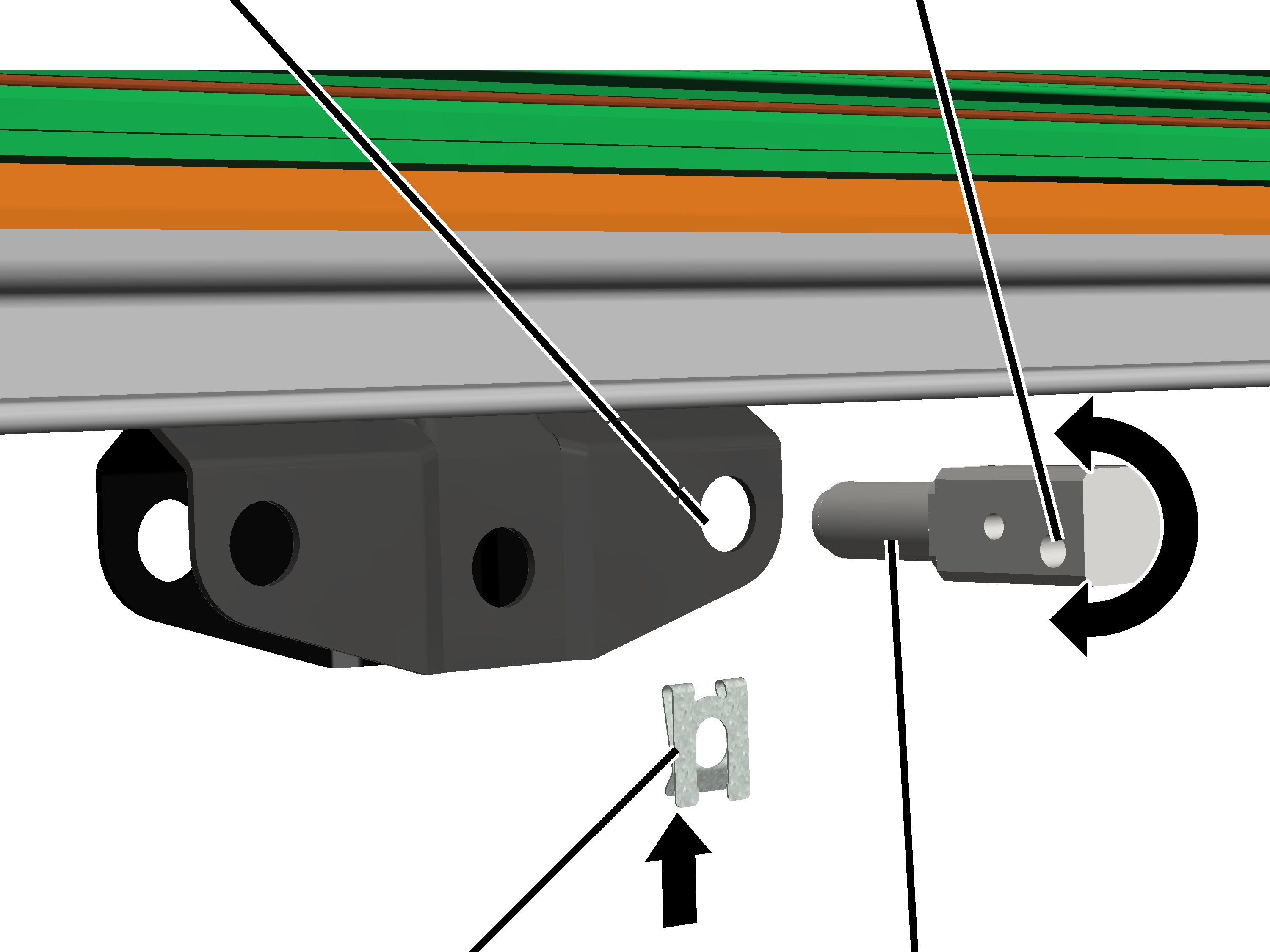
|
Outer drilled hole | |
|
| |
|
SL safety clip |
Carrier shaft |
Turn the carrier shaft
with the outer drilled hole toward the top or toward the bottom.
|
Size |
Outer drilled hole in the carrier shaft |
|
HB240S |
Toward the top |
|
HB190A HB190S |
Toward the top |
|
HB150A HB150S |
Toward the bottom |
Insert the SL safety
clip.
|
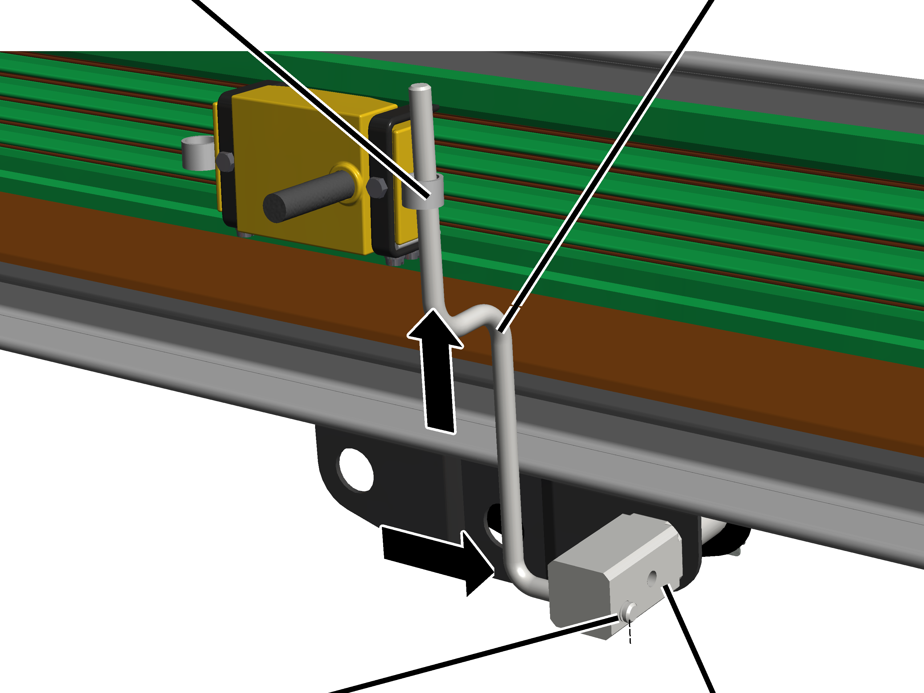
Right eyelet on the current collector |
Towing mandrel |
|
| |
|
Outer hole in the carrier shaft |
Inner hole in the carrier shaft |
Rotate the towing mandrel
as in the diagram.
Insert the towing mandrel
from below into the right eyelet on the current collector.
Insert the towing mandrel
from the left into the outer hole in the carrier shaft.
Secure the towing mandrel
with the SL safety clip.
Tip:
The assembly described above ensures that the current collector is positioned centred over the trolley. The current collector will therefore not bump against the end of the HB profile rail.
Summary:
─ Insert the carrier shaft into the right drilled hole on the trolley.
─ Insert the towing mandrel from the left into the carrier shaft.
─ Insert the towing mandrel into the right eyelet on the current collector.
Depending on the crane installation, the towing mandrel may protrude at the top over the conductor system VKL. If the towing mandrel causes problems (e.g. catches on things), it must be shortened.
If the towing mandrel protrudes at the top and is a problem:
|
|
Protruding towing mandrel |
|
| |
Saw or cut off the end of
the towing mandrel.
On the towing mandrel is a notch to be used for shortening it.
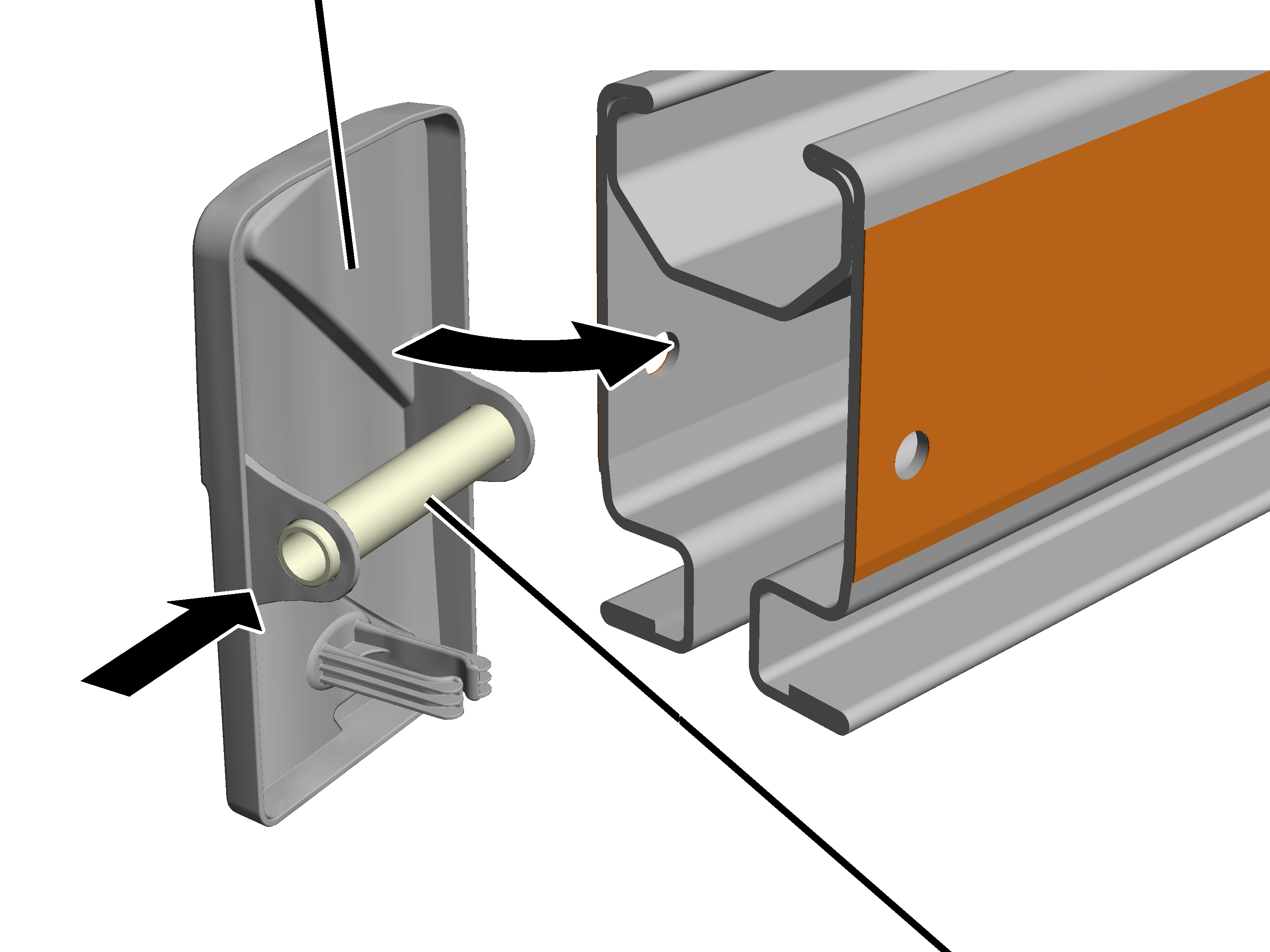
On both ends of the conductor system:
|
|
Retaining cap |
|
| |
Place the retaining cap on
the conductor system.
Securely bolt the
retaining cap from the back side with self-drilling screws (2x).
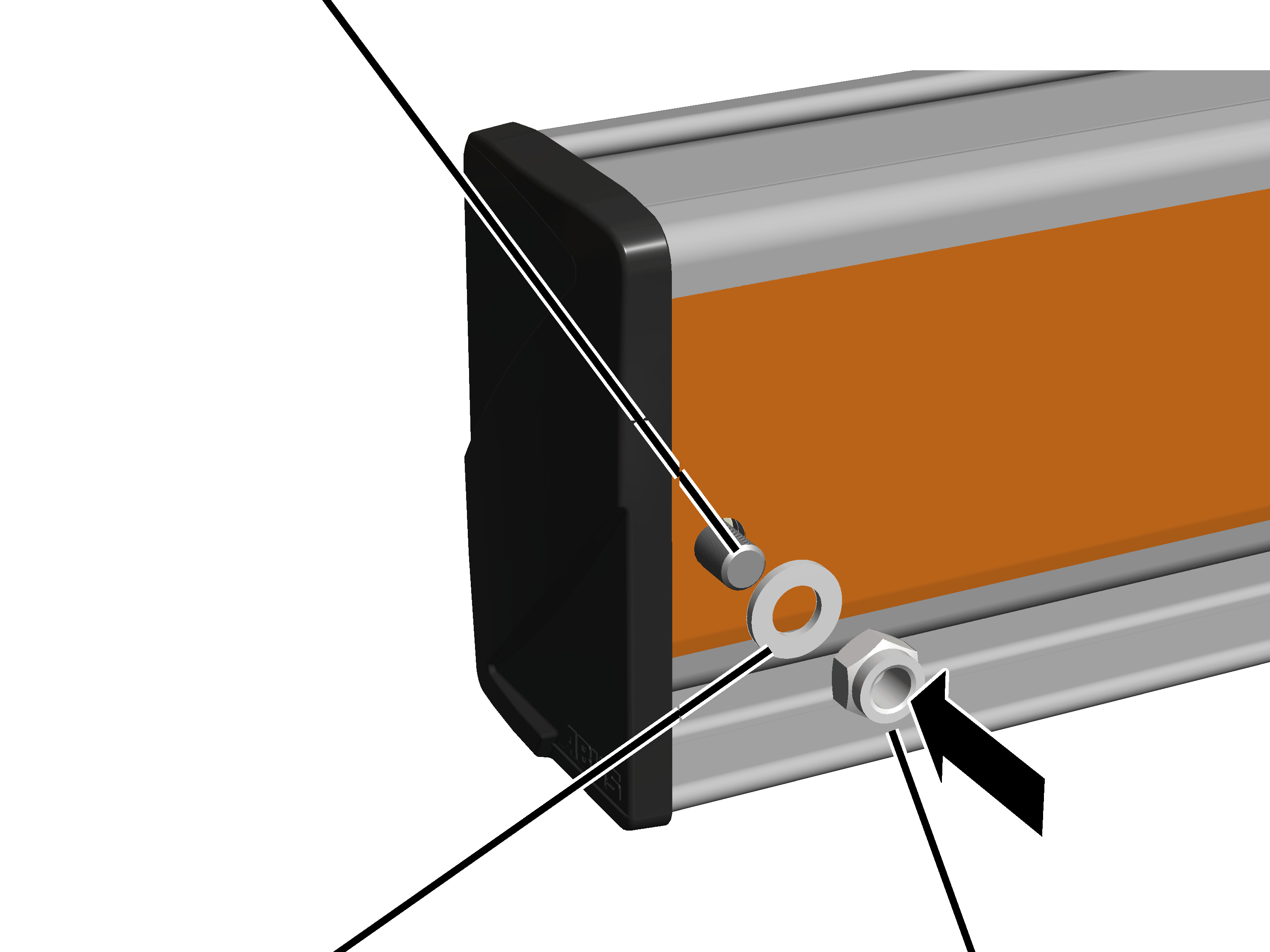
Every HB profile rail must be fitted with end caps on the profile ends. These prevent dirt from penetrating the HB profile rail and also serve as an end stopper to prevent the HB crane or trolley from falling out of the HB profile rail.
On the front and back of all HB profile rails:
|
End cap |
|
|
| |
|
|
Spacer sleeve |
Push the spacer sleeve
into the end cap.
Only with HB240: use the spacer sleeve with black coating. It is slightly longer than the spacer sleeve with silver or yellow coating.
Put on the end cap.
If necessary, widen the HB profile rail slightly to enable insertion of the spacer sleeve.
|
Hexagon head screw |
|
|
| |
|
Washer |
Self-locking M12 nut |
Insert a hexagon head
screw through the HB profile rail and the spacer sleeve.
|
Size |
Hexagon head screw |
|
HB150 |
M12x110 |
|
HB190 |
M12x110 |
|
HB240 |
M12x110 |
Insert washer, screw on
the self-locking M12 nut. 80 Nm.