The figures show the installation of a steel HB profile rail of size HB150S. The installation of larger or smaller HB profile rails or aluminium HB profile rails does not differ significantly from this.
Normally the profile rail sections are cut to the corresponding length for the specific order. This eliminates the need to cut the profile rail sections on-site.
Especially with reconstructions, it may be necessary to shorten the profile rail sections on-site.
|
|
The figures show the installation of a steel HB profile rail of size HB150S. The installation of larger or smaller HB profile rails or aluminium HB profile rails does not differ significantly from this. |
Note:
In order for the HB crane or the trolley to later run smoothly and without jolts in the area of a profile joint, high accuracy is required when sawing the profile rail sections. This accuracy can only be achieved with a special sawing fixture.
For this reason, it is only permitted to saw profile rail sections which are mounted at the end of the crane track/crane girder. Profile rail sections may not be cut at a profile joint on-site.
If an existing HB crane installation is expanded, a saw-cut profile rail section at the end of the crane track / crane girder must be disassembled and replaced by a full-length profile rail section. The saw-cut profile rail section can be reinstalled at the end of the expanded HB crane installation.
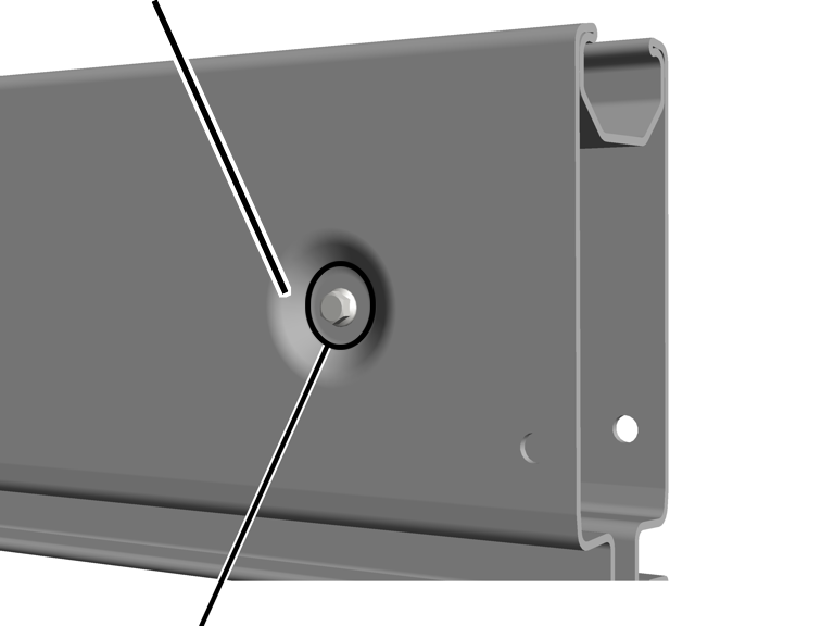
If the profile rail section is to be sawed off near a crosswise screw fitting, the crosswise screw fitting must first be removed.
|
Inclined area on the bead |
|
|
| |
|
Level inside surface of the bead |
|
 Check if the saw cut is in
the area of a transverse screw connection.
Check if the saw cut is in
the area of a transverse screw connection.
If sawing must be performed near the level inner surface of the bead, the crosswise screw fitting must be removed.
If sawing is performed in the inclined area of the bead, the crosswise screw fitting can remain mounted.
|
|
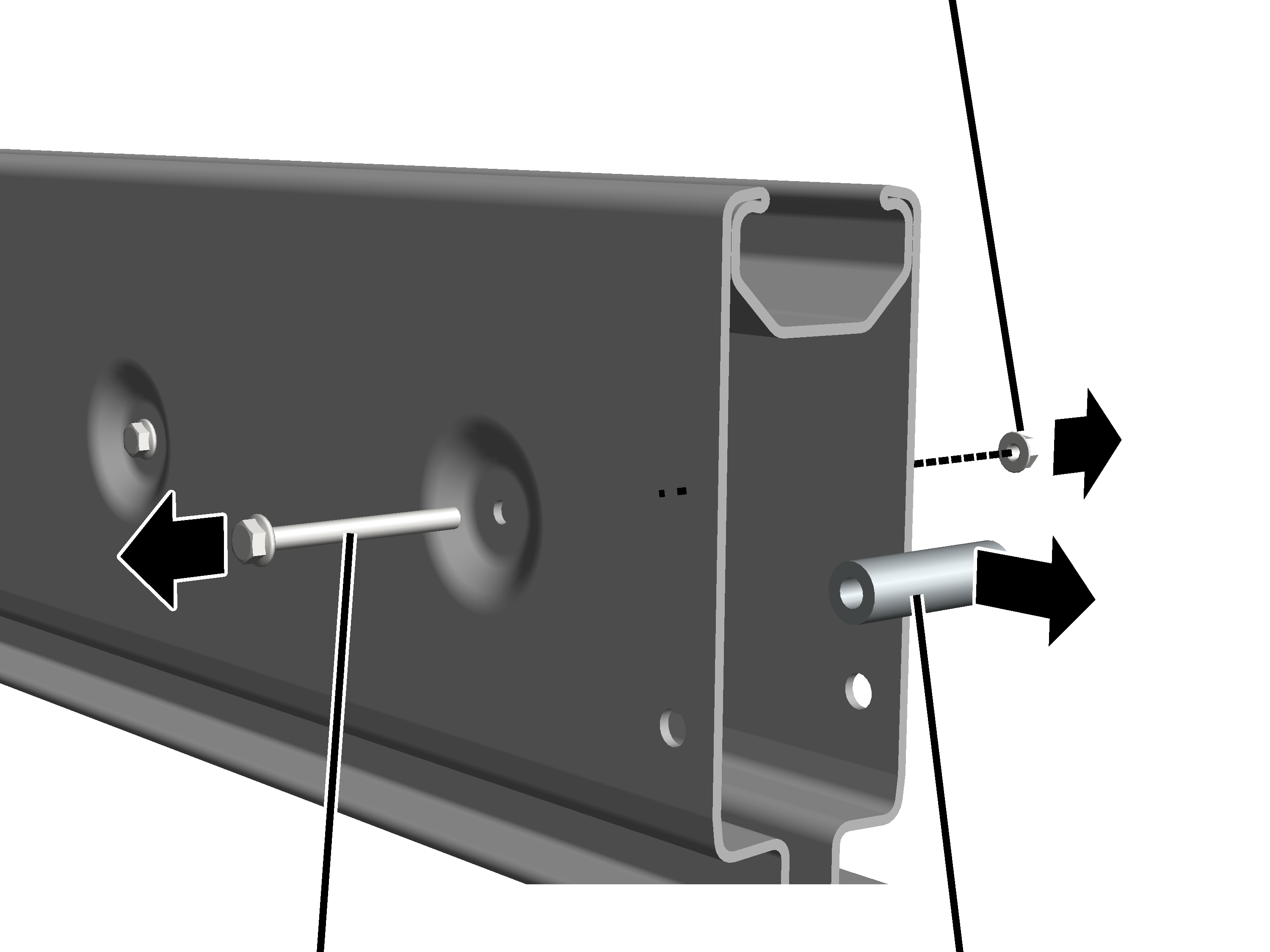
Rib nut M8 |
|
| |
|
Rib screw M8x80 |
Spacer sleeve |
Release rib screw M8x80
and rib nut M8.
Remove the spacer sleeve
from the HB profile rail.
Rib screw, rib nut and spacer sleeve are no longer needed.
Sawing a profile rail section at the beginning or end:
|
|
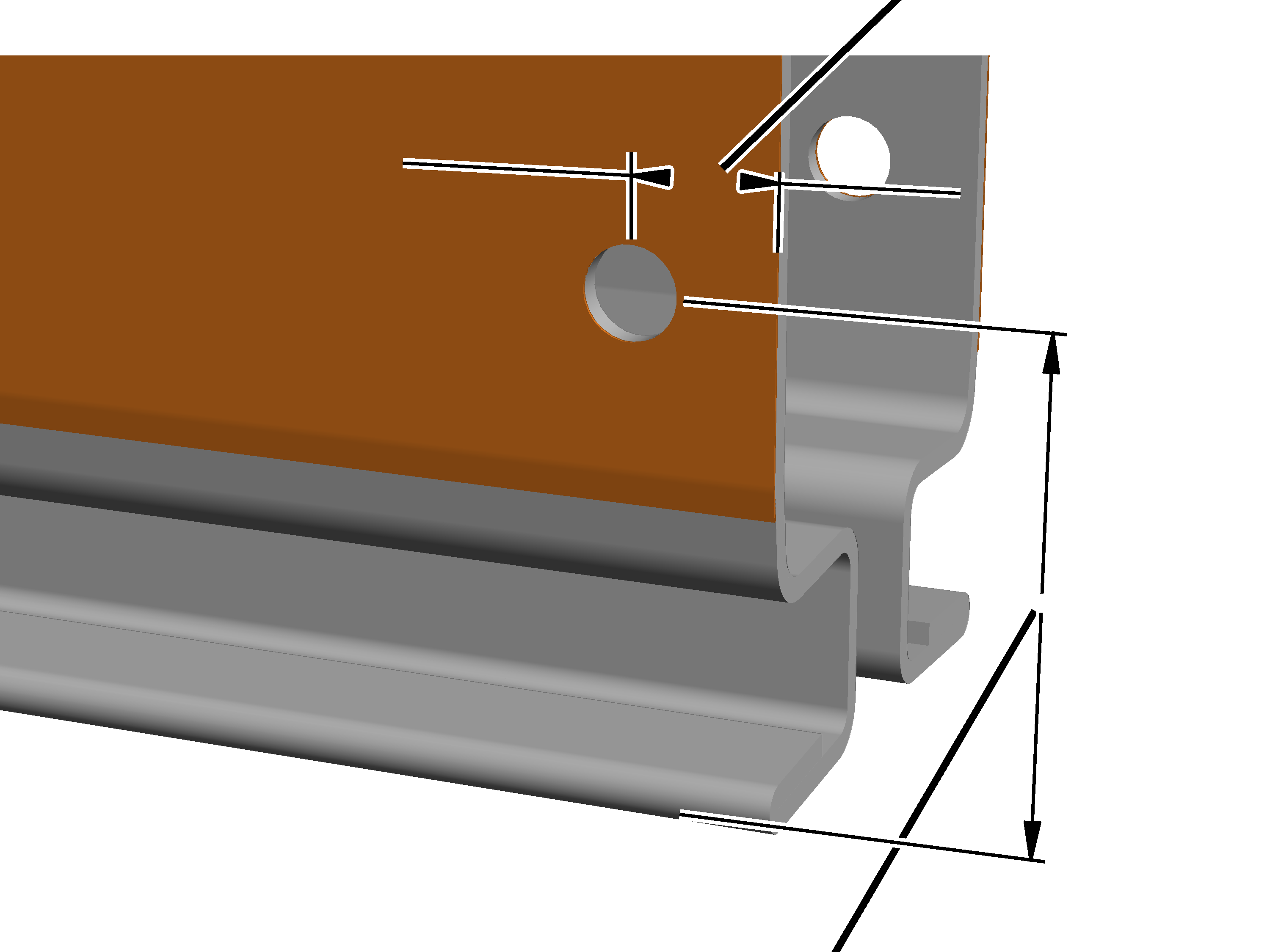
Distance to cut edge 20 mm |
|
| |
|
|
Distance to lower edge |
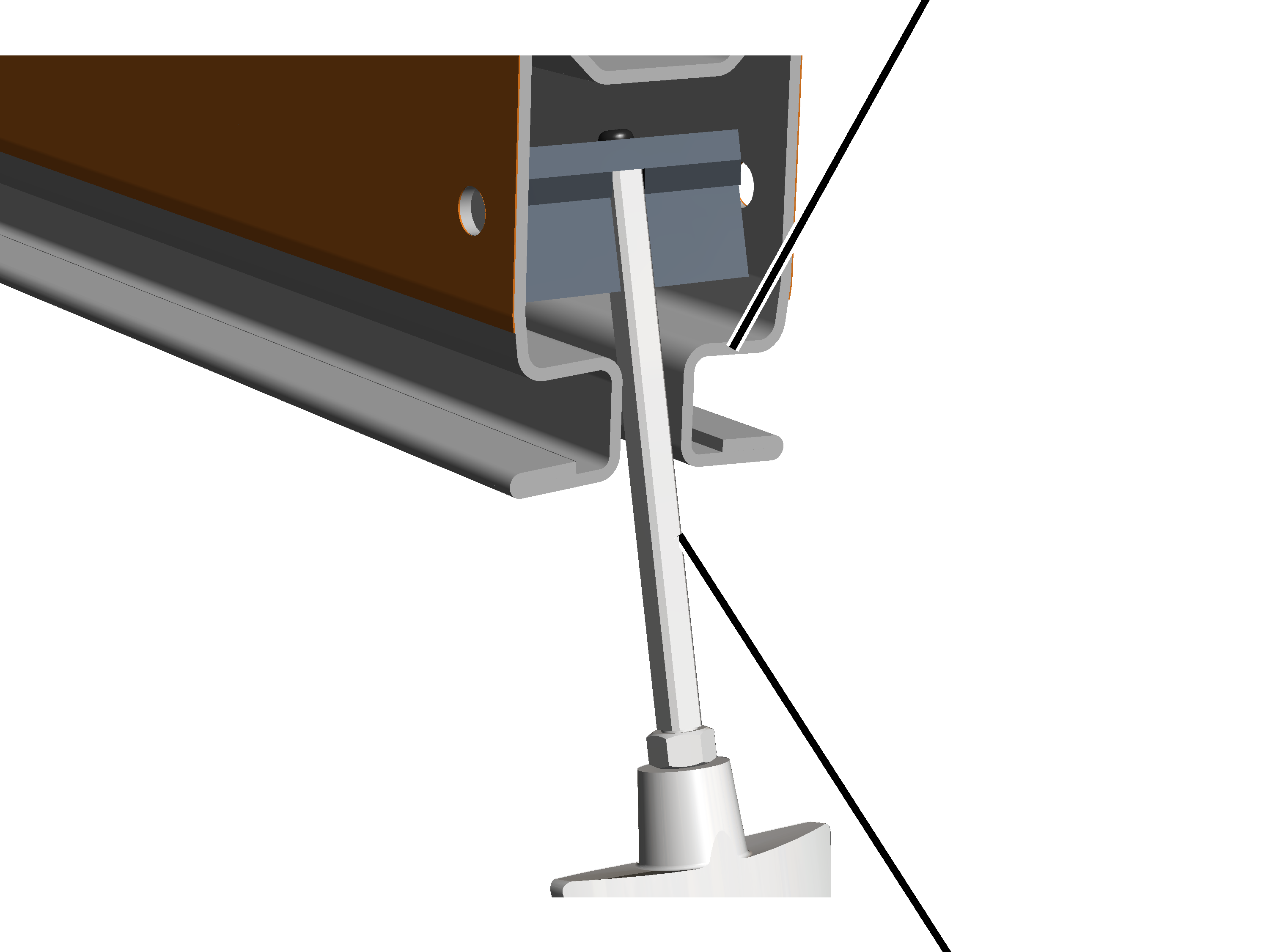
Turn the profile rail
section so the opening is facing down.
This allows shavings to fall out of the profile rail section so they do not accumulate inside it.
Saw off the profile rail
section at a perpendicular angle at the desired point.
Drill a hole in the
profile rail section on both sides for the end cap.
─ Diameter 13 mm.
─ 20 mm from the sawed edge
─ Distance to lower edge
|
Size |
Distance |
|
HB150 |
73 mm |
|
HB190 |
73 mm |
|
HB240 |
73 mm |
Deburr the drilled
holes.
|
|
Running surface |
|
| |
|
|
Brush |
Remove any saw or drill
shavings on the inside; particularly from the running surface at the travel gap.
Otherwise the shavings can clog the castors of the trolleys and impair their running.
A special brush can be used for the simple and effective cleaning of the running surface. The brush can be obtained from ABUS Service. AN 315909. See ABUS Service.