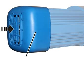
Fan cover
When replacing the fan blade with brake lining, it is recommended that the anchor plate be replaced as well.
|
| |
|
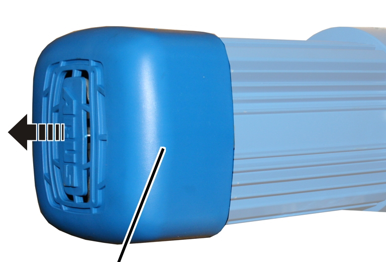
Fan cover |
|
 Take off the fan
cover.
Take off the fan
cover.
|
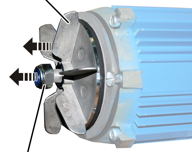
Fan blade with brake lining | |
|
| |
|
Self-locking nut |
|
Hold the fan blade firmly
and unscrew the self-locking nut.
Remove the fan blade with
brake lining.
When replacing the fan blade with brake lining, it is useful to replace the anchor plate as well. If the anchor plate is not to be replaced, this section may be skipped.
|
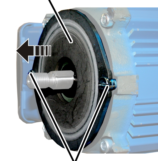
Anchor plate |
|
|
| |
|
Collar screws |
|
Screw the collar screws
(2x) out.
● The anchor plate is pressed away from the motor. It is tensioned by a spring.
Remove the anchor plate.
Ensure that the compression springs do not fall out.
If the O-ring, plate springs, compression springs or the feather key are missing or damaged, they must be replaced. If the components are in a good condition, this section may be skipped.
|
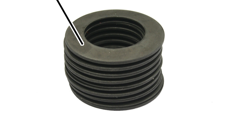
Plate springs |
|
|
| |
Assemble the plate springs
as shown in the illustration.
|
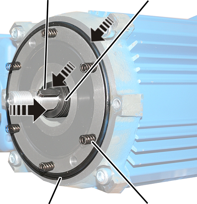
Feather key |
Plate springs |
|
| |
|
O-ring |
Compression springs |
Push the plate springs
onto the motor shaft.
Insert the feather
key.
Place the O-ring into the
groove on the brake bearing shield.
 Insert the compression
springs.
Insert the compression
springs.
|
Type & size |
Power (see type plate) |
Number of compression springs |
|
E 100 |
0.12 kW |
4 |
|
E 130 / AZP 130 |
0.18 kW |
4 |
|
E 160 / AZP 130 |
0.28 kW |
6 |
|
AZP 130 |
0.37 kW |
8 |
|
E 200 / AZP 160 |
0.48 kW |
4 |
|
AZP 200 / AZP 280 |
0.65 kW |
4 |
|
AZP 200 / AZP 280 |
0.80 kW |
6 |
|
AZP 280 |
1.10 kW |
8 |
|
|
|
Compression springs |
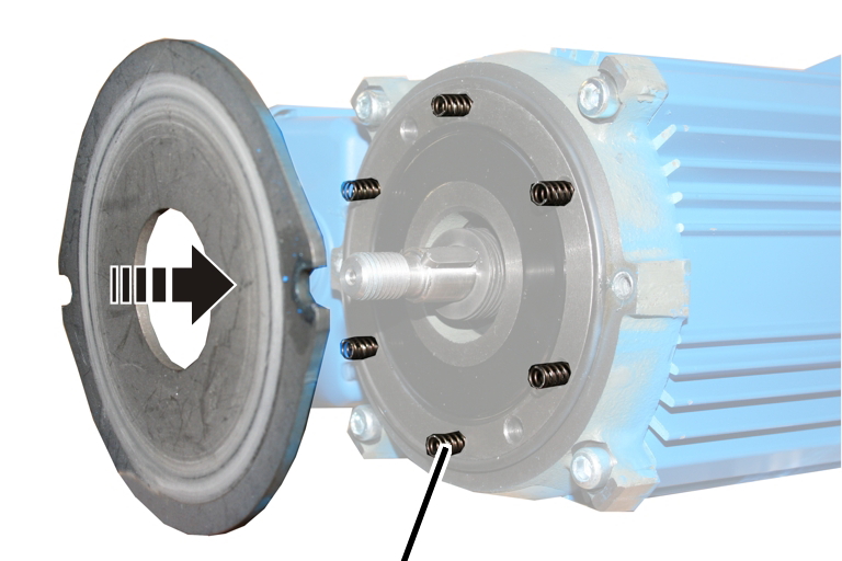
Insert new anchor plate
and press it against the compression springs.
Tighten the collar screws
(2x). 5 - 7 Nm. Secure with thread-locking compound (medium
tightness).
|
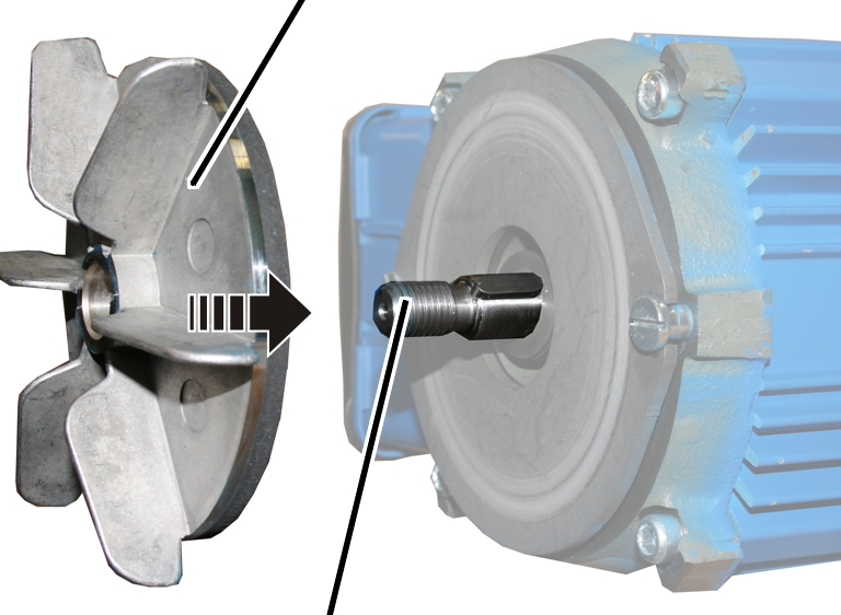
Fan blade with brake lining |
|
|
|
Motor shaft |
Slide the new fan blade
with brake lining onto the motor shaft.
Screw the new self-locking
nut loosely to the motor shaft.
Do not use the old self-locking nut.
|
| |
|
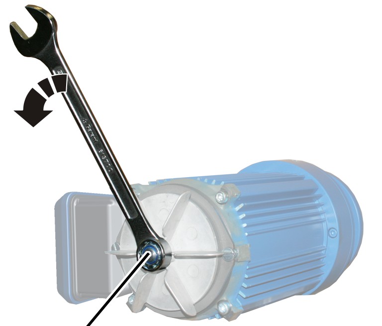
Nut |
|
Hold the fan blade firmly
and screw the self-locking nut until hand-tight. The fan blade should just be
tight enough that it almost cannot be turned.
● The air gap is now set to 0 mm. This serves as the starting point for the following setting.
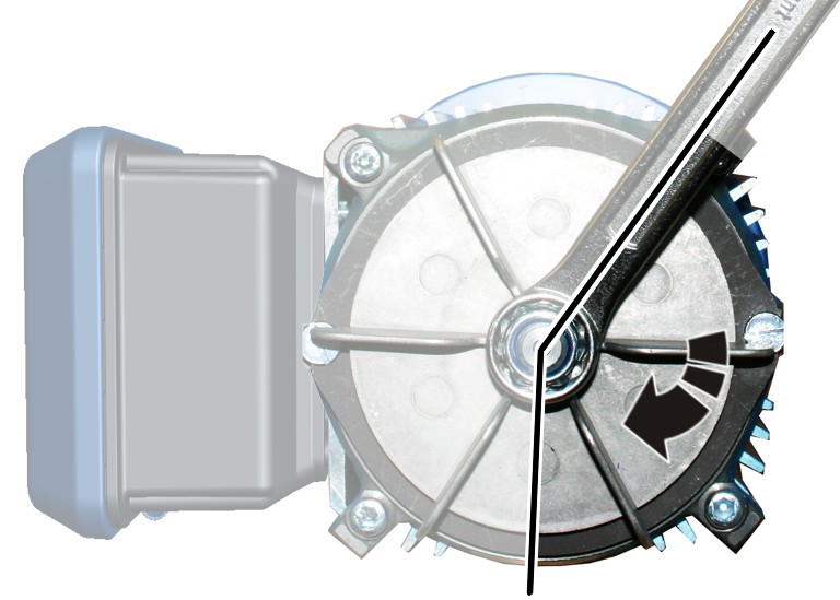
The self-locking nut is now released in order to optimally adjust the air gap of the brake. The releasing of the self-locking nut is oriented to the individual segments of the fan blade.
|
|
Hold the fan blade firmly
and release the self-locking nut by the amount of two and one half segments of
the fan blade.
● The air gap is now set to the optimal width of 0.4 mm.
To make sure, check that
the distance between the brake bearing shield and the anchor plate (reference
gap) is between 3.1 mm and 3.7 mm. See Checking the brake on the trolley
drive.
|
| |
|
Fan cover |
|
Attach fan cover.