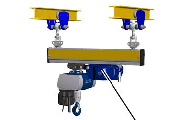
Trolley drive
The HBF drive is then installed as an electric trolley drive.
|
|
|
Trolley drive |
|
|
The figures show the installation of a steel HB profile rail of size HB150S. The installation of larger or smaller HB profile rails or aluminium HB profile rails does not differ significantly from this. |
|
|
Where an HBF drive is to be installed is specified in the planning documents. |
The HBF trolley drive can be connected to the trolley on the friction wheel side or on the travel motor side. How the connections around the drive are made depends on the on-site conditions.
This section only applies if the HBF drive is to be connected to the trolley on the friction wheel side.
On every HBF drive:
|
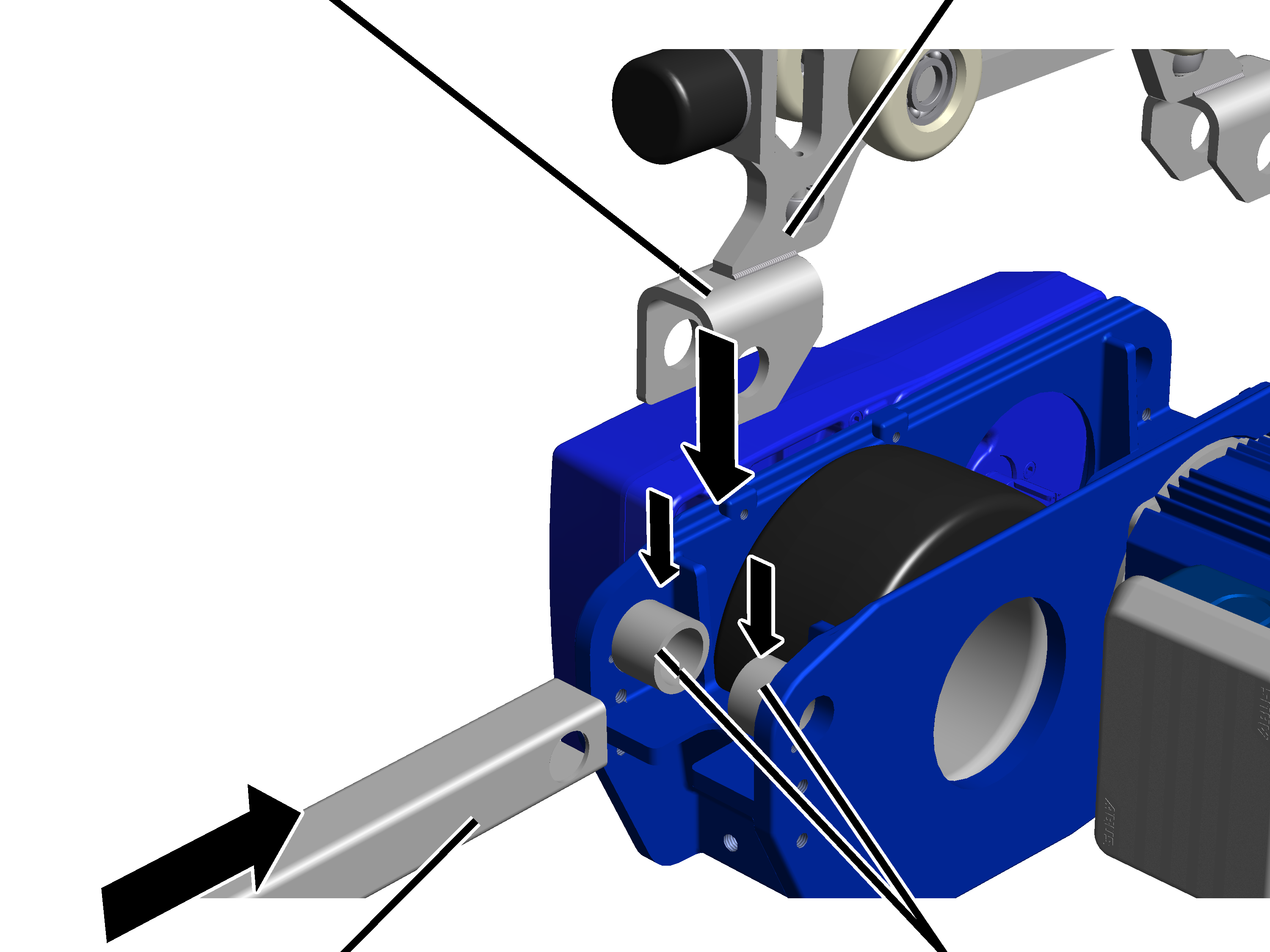
Fork part |
HBF trolley |
|
| |
|
Coupling bar |
Bush (2x) |
 Push the coupling bar
between the fork part from the front.
Push the coupling bar
between the fork part from the front.
|
|
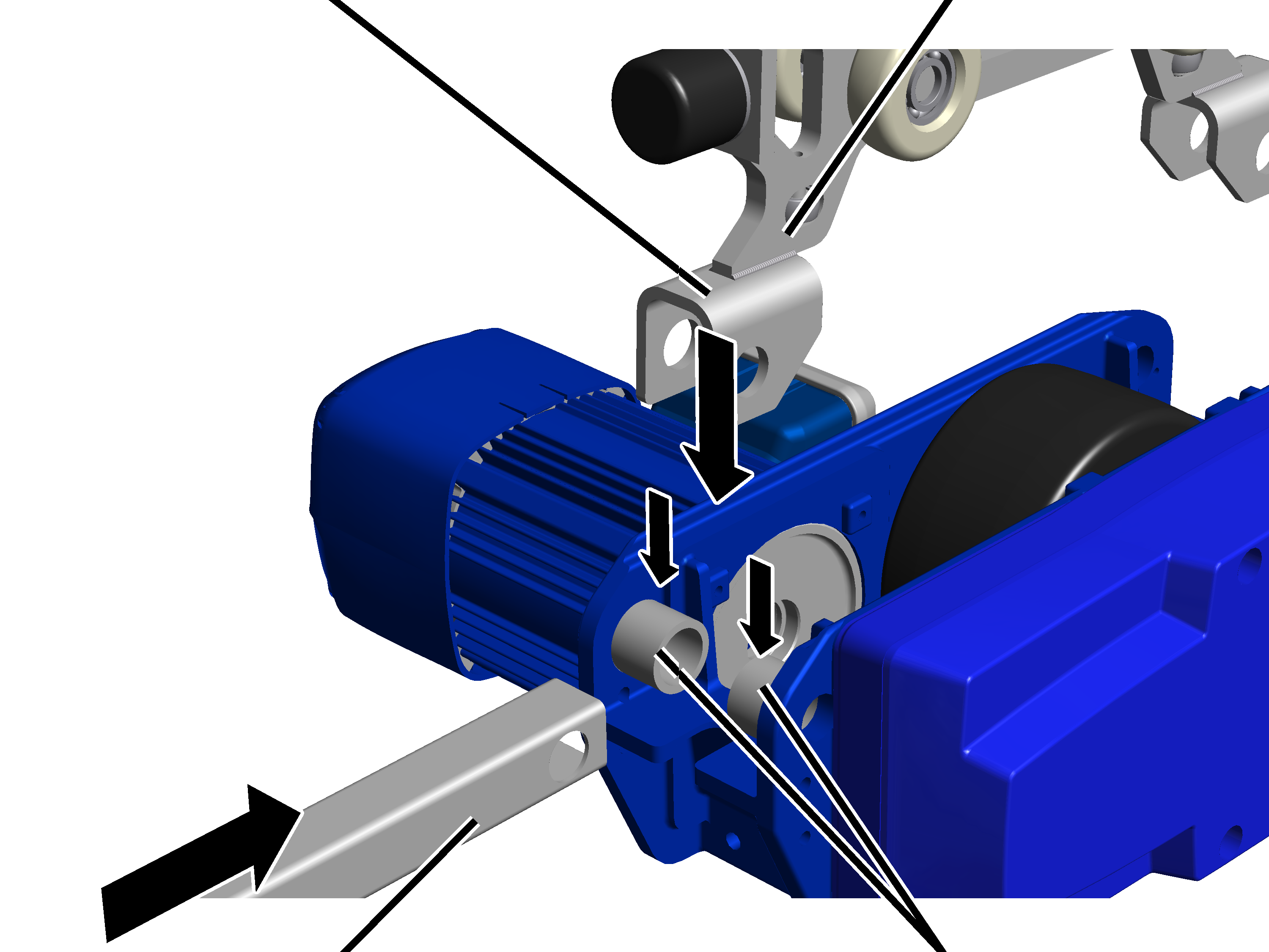
Bolt |
|
| |
|
|
Rib screw M5x10 |
Push the bolt laterally through the HBF drive, the
bushes, the fork part and the coupling bar.
Screw the rib screw M5x10
(2x) in next to the bolt. 11 Nm.
● The bolt is fixed in place from both sides by the rib screw.
|
Coupling (only with anti-collision device as preceding trolley) | |
|
| |
|
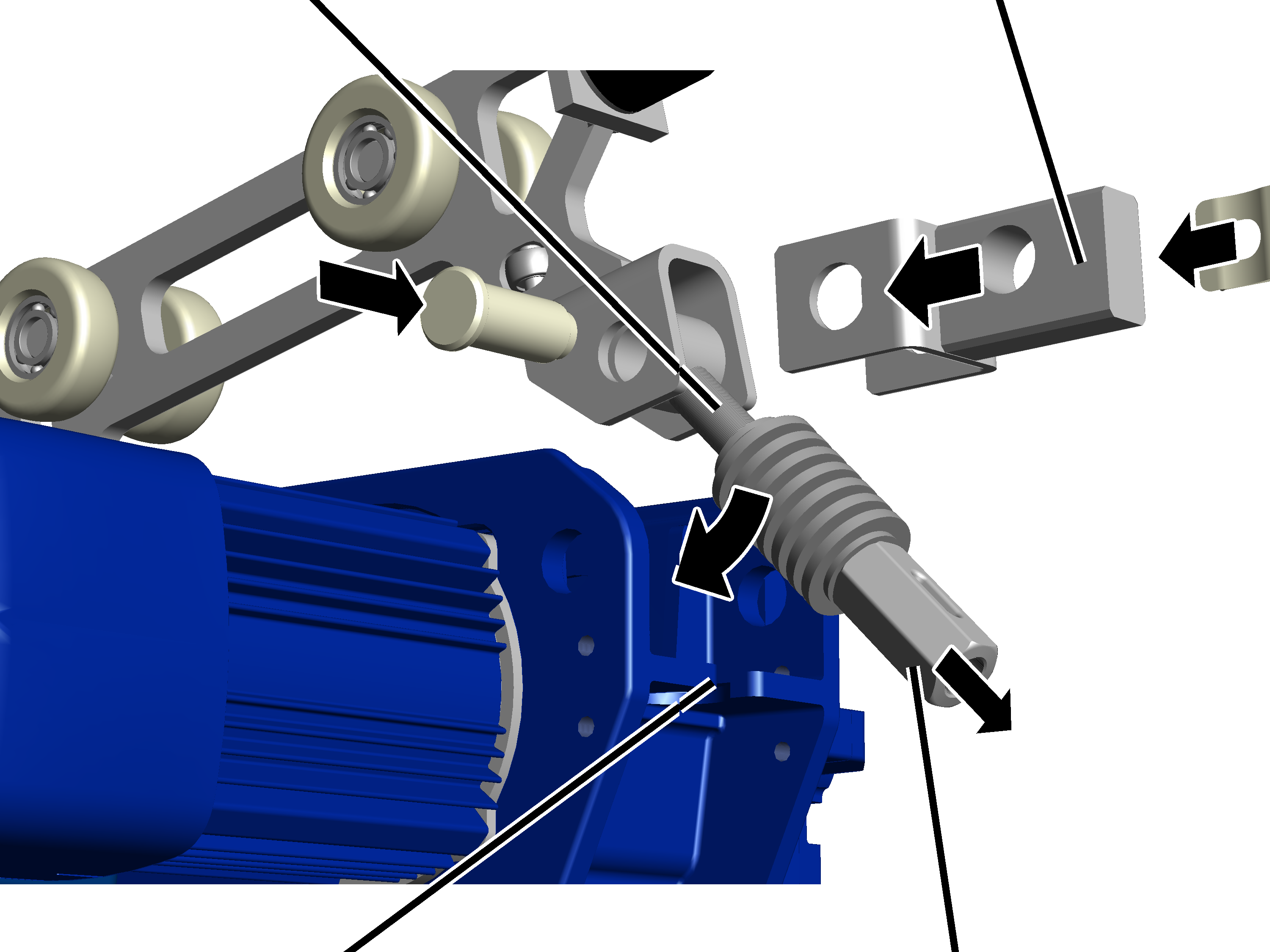
Recess on HBF drive |
Coupling |
On the other side on the
HBF drive, insert the eyebolt inside the fork part.
Only with anti-collision
device as preceding trolley or with coupling bar: if, on the HBF drive side, an
anti-collision device as preceding trolley or an anti-collision device with
coupling bar is to be installed, push a coupling over the fork part.
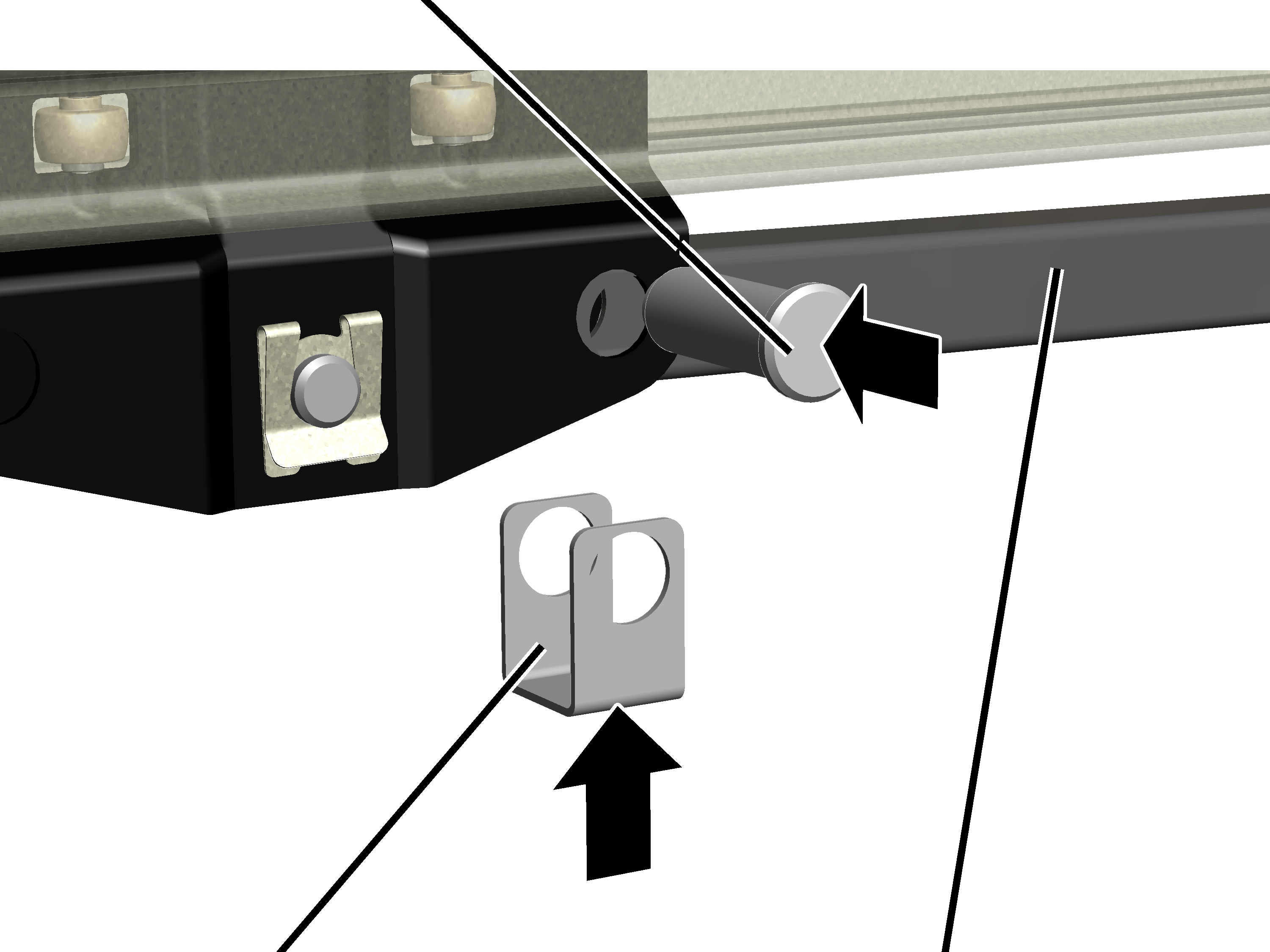
Push the bolt through the
fork part and eyebolt (and coupling if appropriate).
Secure bolt with SL safety
clip.
Unscrew the coupling from the eyebolt until it is
only a few turns from the end.
● This allows the eyebolt to be suspended without counter-pressure from the plate springs.
Hook the eyebolt in the
recess on the HBF drive. The plate spring pack then goes under the recess on the
HBF drive.
|
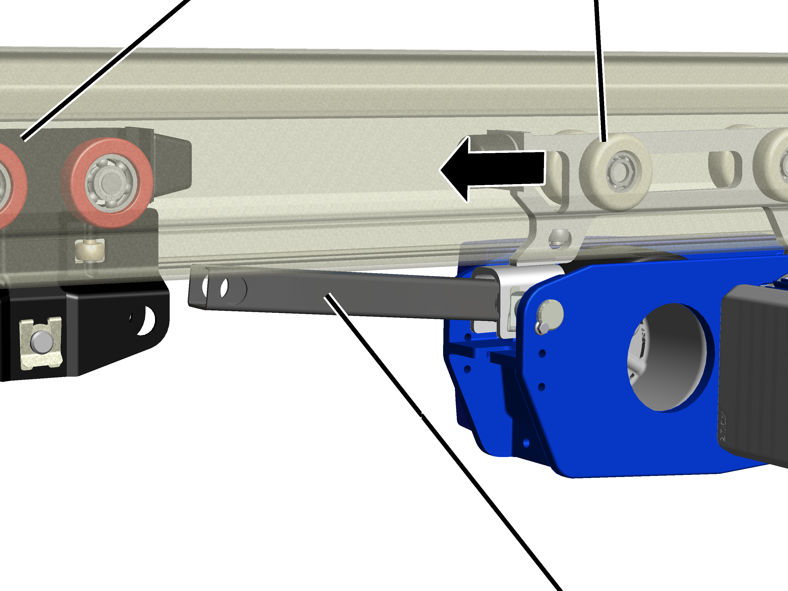
Travel mechanism of the trolley |
HBF trolley |
|
| |
|
|
Coupling bar |
Turn the HBF drive so that
the coupling bar points toward the trolley on which the HBF drive is to be
fixed.
Push the HBF drive with
HBF trolley into the HB profile rail.
|
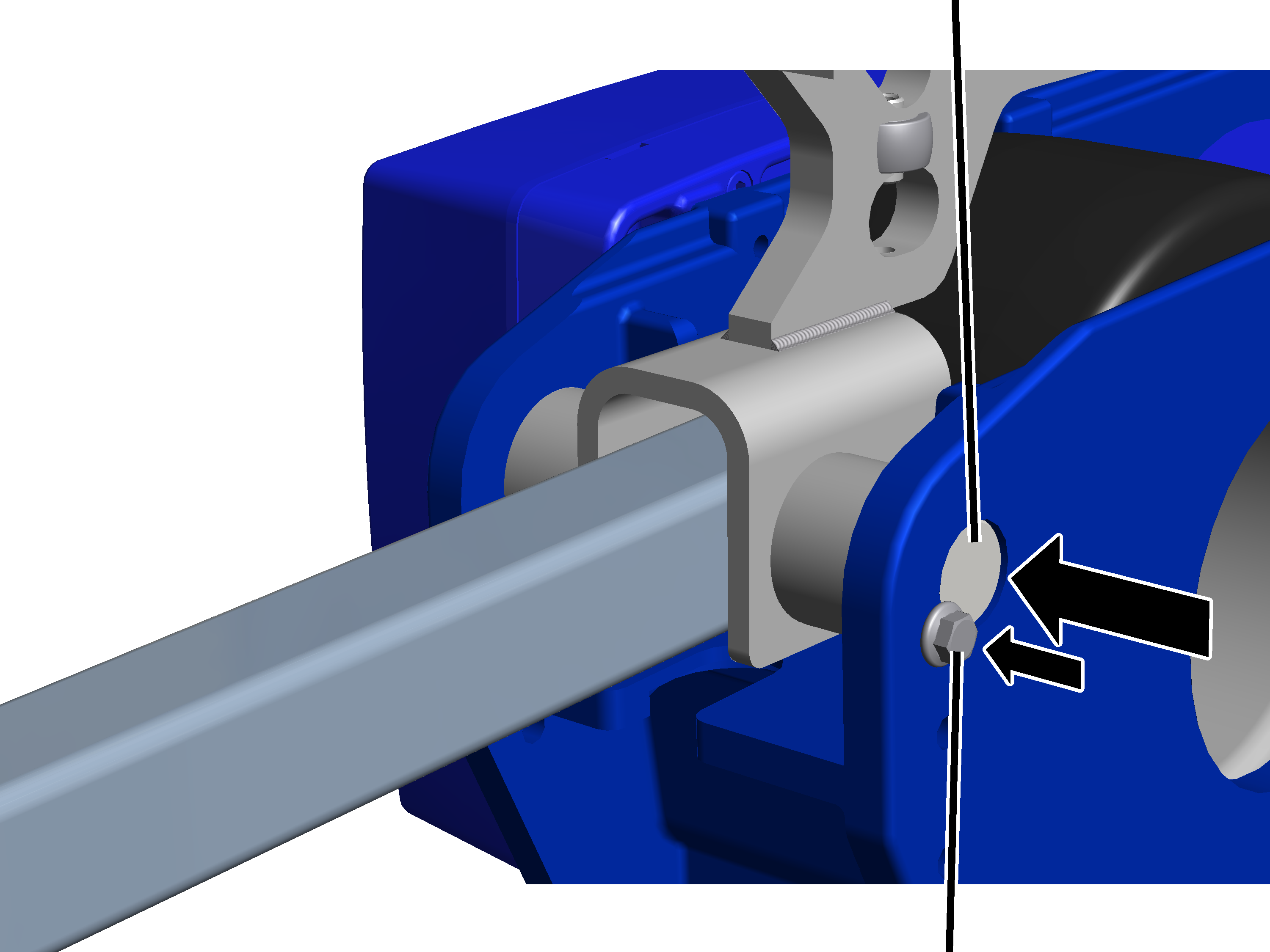
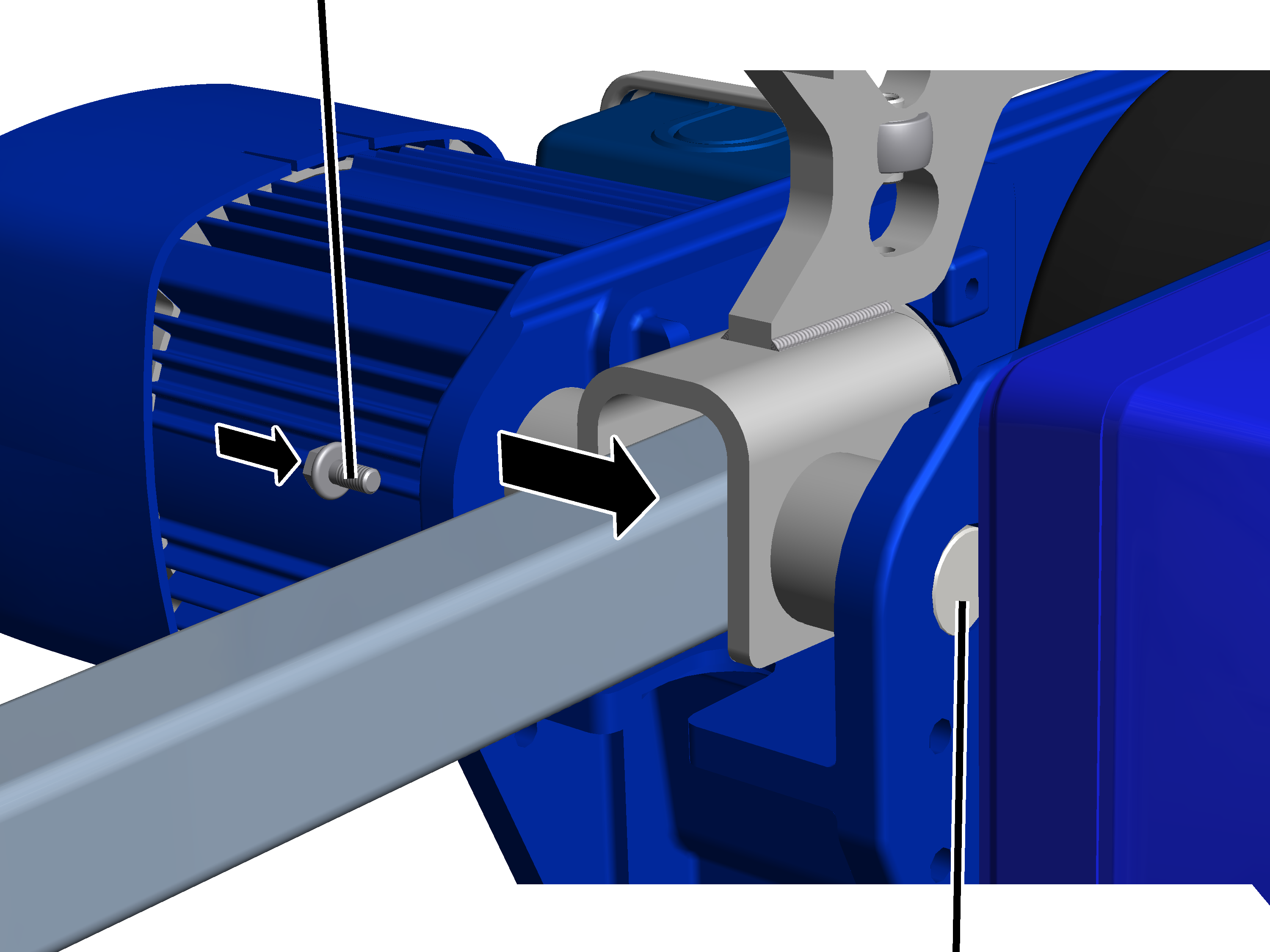
Bolt |
|
|
| |
|
Spacer bracket |
Coupling bar |
Push the HBF drive with
the coupling bar up to the trolley.
The coupling bar is fixed in the hole facing the HBF drive.
Insert a spacer bracket between trolley and coupling
rod.
Insert bolt through
trolley and coupling bar.
Secure bolt with SL safety
clip.
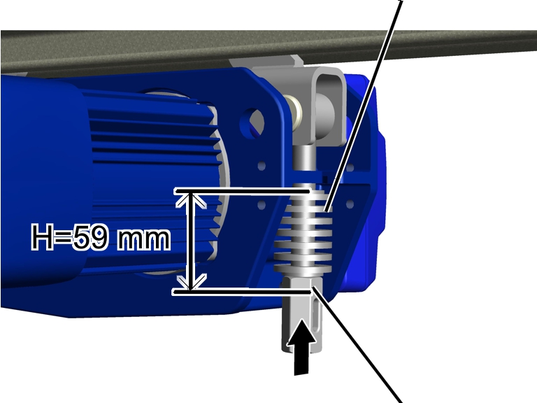
The plate springs serve in setting the pressure with which the friction wheel presses the HBF drive against the HB profile rail.
|
|
|
Plate springs |
|
|
| |
|
|
|
Coupling |
Turn the coupling until
the plate springs (including the upper and lower discs) are H = 59 mm in
length.
Secure coupling with
spring cotter.
● The friction wheel now presses hard enough against the HB profile rail.
This section only applies if the HBF drive is to be connected to the trolley on the travel motor side.
On every HBF drive:
|
Fork part |
HBF trolley |
|
| |
|
Coupling bar |
Bush |
Bring the left and right
bushes (2x) as well as the fork part to the centre between the HBF drive on the
travel motor side.
Push the coupling bar
between the fork part from the front.
|
Rib screws M5x10 | |
|
| |
|
|
Bolt |
Push the bolt laterally
through the HBF drive, the bushes, the fork part and the coupling bar.
Screw the rib screw M5x10
(1x) in next to the bolt. 11 Nm.
● The bolt is fixed in place on one side by the gear unit and on the other side by the rib screw.
|
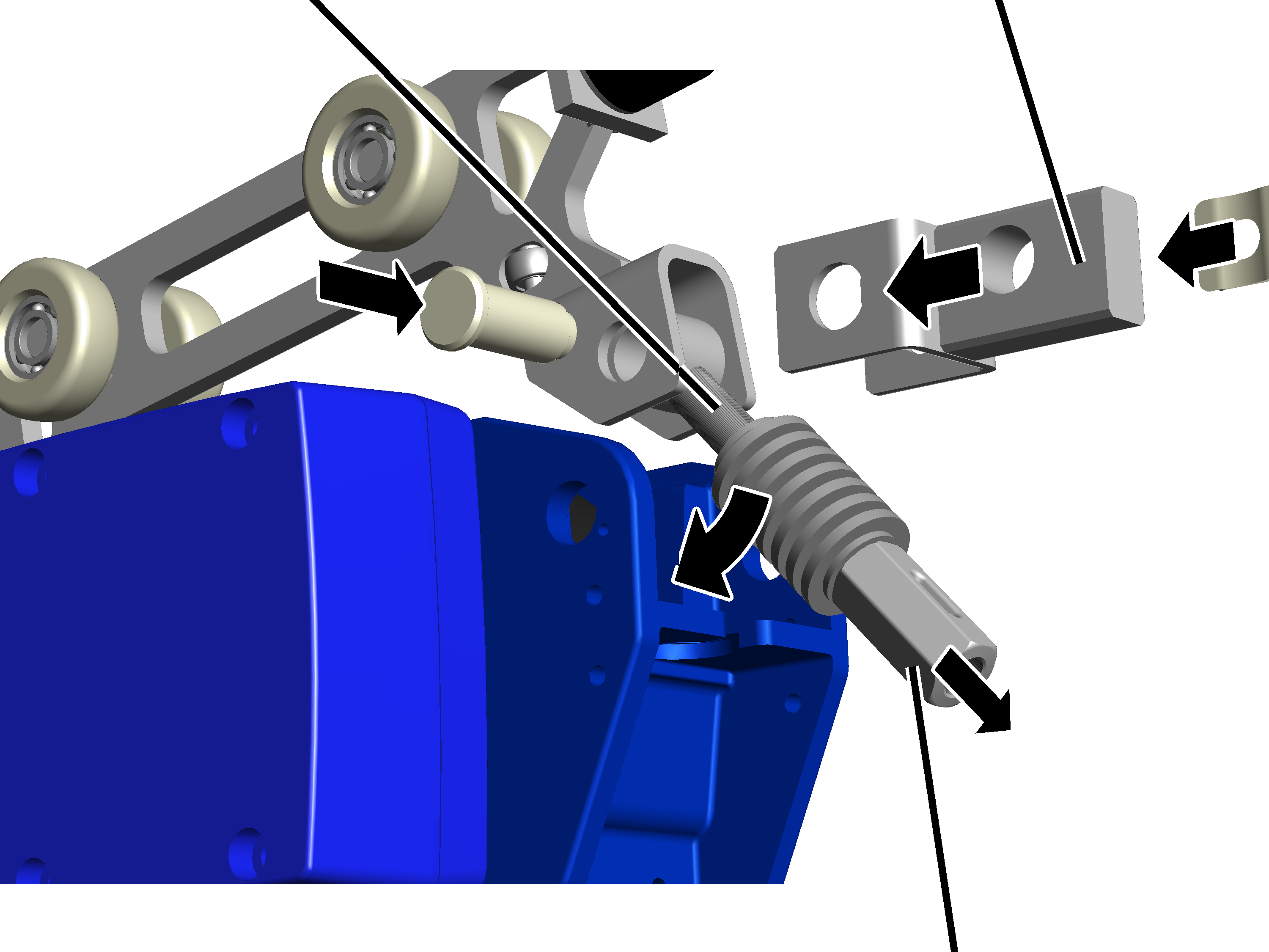
Eyebolt |
Coupling (only with anti-collision device as preceding trolley) |
|
| |
|
|
Coupling |
 On the other side on the
HBF drive, insert the eyebolt inside the fork part.
On the other side on the
HBF drive, insert the eyebolt inside the fork part.
Only with anti-collision
device as preceding trolley or with coupling bar: if, on the HBF drive side, an
anti-collision device as preceding trolley or an anti-collision device with
coupling bar is to be installed, push a coupling over the fork part.
Push the bolt through the
fork part and eyebolt (and coupling if appropriate).
Secure bolt with SL safety
clip.
Unscrew the coupling from
the eyebolt until it is only a few turns from the end.
● This allows the eyebolt to be suspended without counter-pressure from the plate springs.
Hook the eyebolt in the
recess on the HBF drive. The plate spring pack then goes under the recess on the
HBF drive.
|
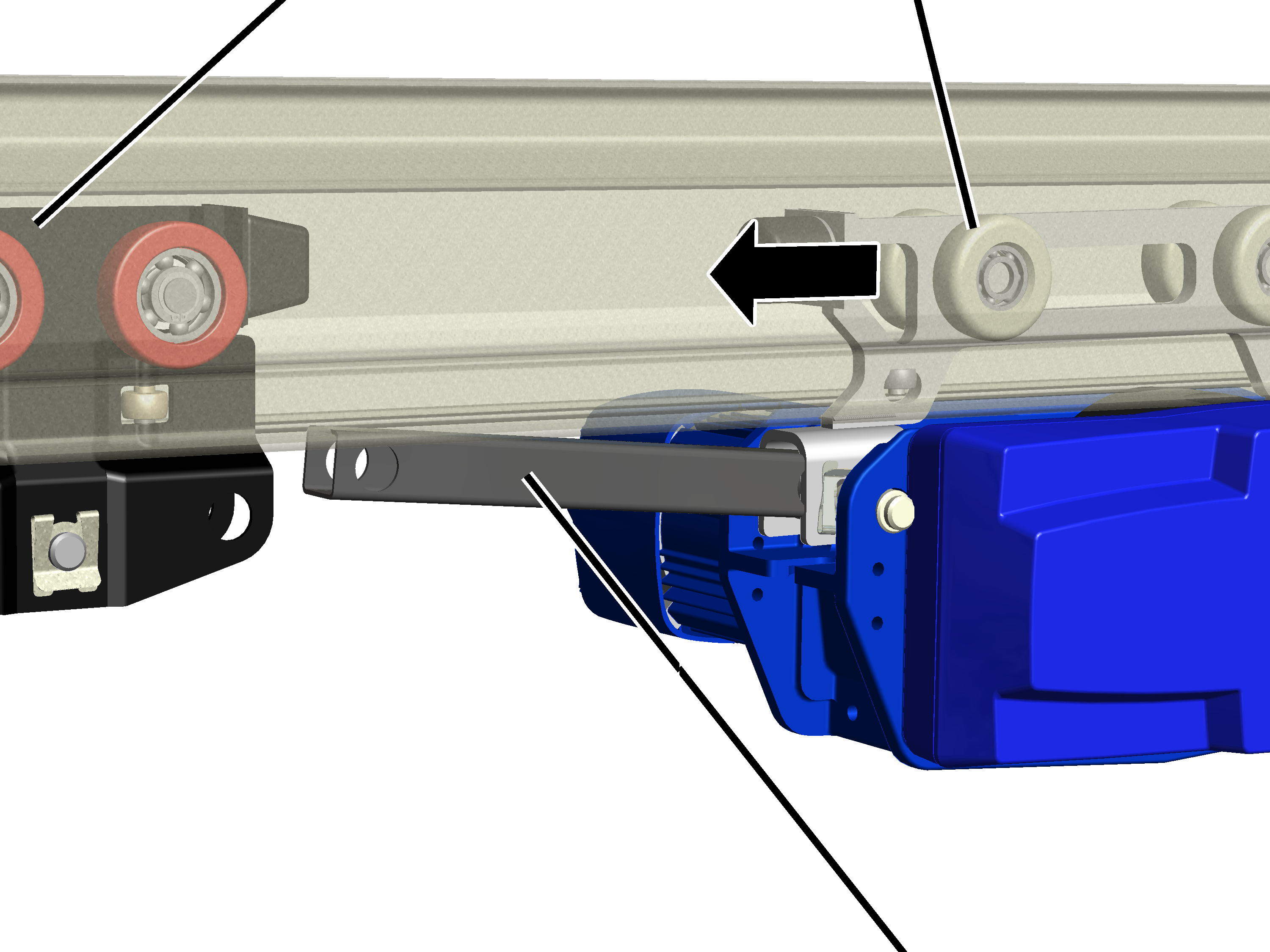
Travel mechanism of the trolley |
HBF trolley |
|
| |
|
|
Coupling bar |
Turn the HBF drive so that
the coupling bar points toward the trolley on which the HBF drive is to be
fixed.
Push the HBF drive with
HBF trolley into the HB profile rail.
|
Bolt |
|
|
| |
|
Spacer bracket |
Coupling bar |
Push the HBF drive with
the coupling bar up to the trolley.
The coupling bar is fixed in the hole facing the HBF drive.
Insert a spacer bracket
between trolley and coupling rod.
Insert bolt through
trolley and coupling bar.
Secure bolt with SL safety
clip.
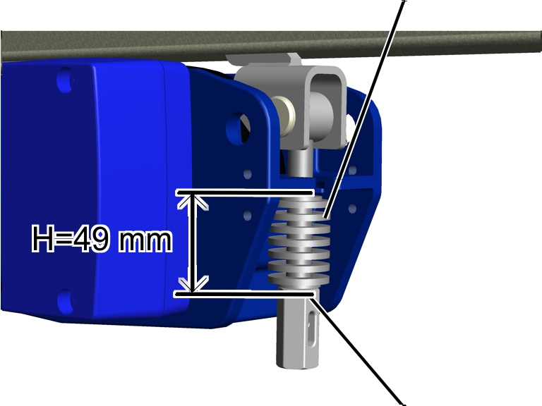
The plate springs serve in setting the pressure with which the friction wheel presses the HBF drive against the HB profile rail.
|
|
Plate springs |
|
| |
|
|
Coupling |
Turn the coupling until
the plate springs (including the upper and lower discs) are H = 49 mm in
length.
Secure coupling with
spring cotter.
● The friction wheel now presses hard enough against the HB profile rail.