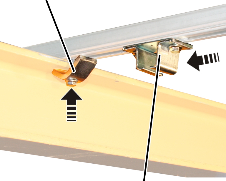
Clamping claw
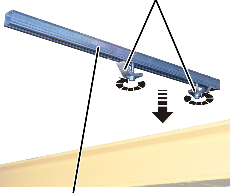
Mounting bracket
The mains power supply is now installed on the I-beam.
The side and position intended for the power supply is specified in the layout plan.
The power supply is available in two versions:
See this section.
─ Conductor system KBH: The power supply consists of a conductor system which is mounted on the I-beam. In the conductor system, a current collector is pulled along by the crane trolley.
See the product manual for the conductor system.
On all installing brackets:
|
|
Clamping claw |
|
| |
|
Mounting bracket | |
 Slide the clamping claws
(2x) into the mounting bracket and align as shown in the illustration.
Slide the clamping claws
(2x) into the mounting bracket and align as shown in the illustration.
From above, place the
mounting bracket onto the I-beam to which the mains power supply is to be
installed.
Where the mains power supply is to be installed is specified in the planning documents.
|
Clamping claw |
| |
|
| ||
|
|
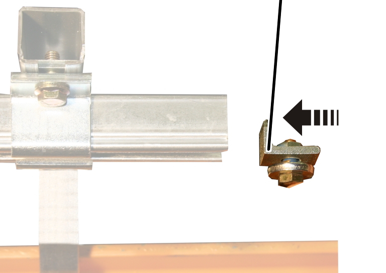
Rail mount | |
 Screw the clamping claw
until hand-tight.
Screw the clamping claw
until hand-tight.
Slide the rail mount in.
Distance to the I-beam 25 cm.
Do not screw the rail
mount tight yet.
|
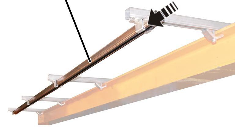
C-rail |
|
|
| |
Slide the C-rail into the
rail mount.
Screw the rail mount
hand-tight.
|
End of the C-rail |
Beginning of the C-rail |
|
| |
|
Rail connector |
|
Attach a rail connector at
the end of an individual C-rail.
Screw the hexagon head
screws hand-tight.
Slide the next C-rail into
the rail mount and insert in the rail connector.
Screw the hexagon head
screws hand-tight.
|
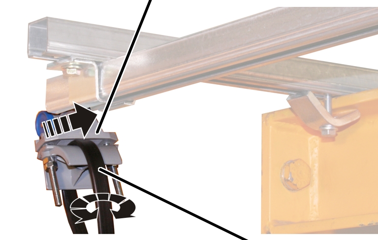
Cable carrier |
| |
|
| ||
|
|
Festoon cable system | |
Turn the cable carrier and
festoon cable system straight. The festoon cable system must not be twisted.
At the end of the C-rail
where the mains switch is attached: Slide all the cable carriers with festoon
cable system one after another into the C-rail.
|
| |
|
|
End terminal |
Last of all, push the end
terminal of the festoon cable system into the C-rail.
Screw the end terminal
hand-tight.
|
|
End stopper |
|
| |
At the other end of the
C-rail: Slide the end stopper into the C-rail.
Screw the end stopper
hand-tight.