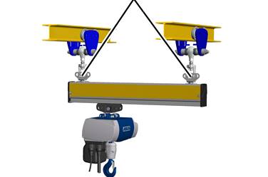
Crane girder suspensions
|
Crane girder suspensions |
|
|
At both ends of the crane girder:
|
| |
|
| |
|
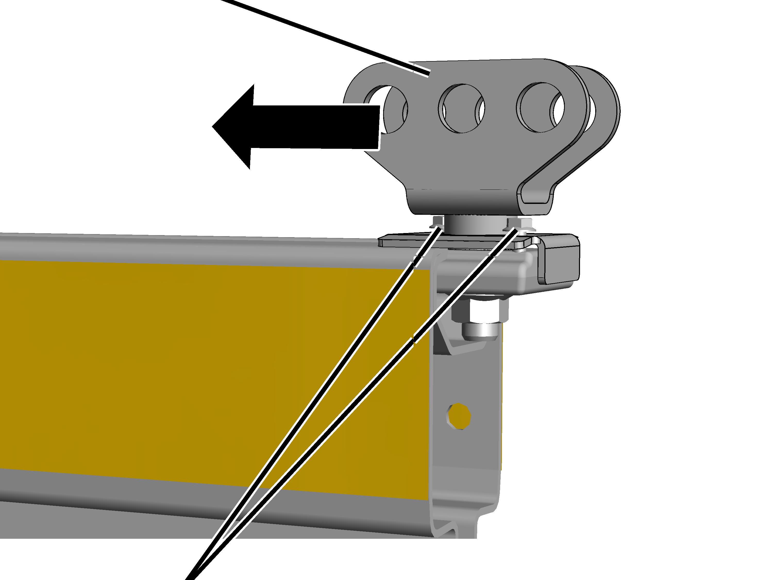
Rib screws |
|
 Refer to the planning
documents for the points intended for the crane girder suspensions. The
specified dimensions, positions and clearances must be followed exactly.
Refer to the planning
documents for the points intended for the crane girder suspensions. The
specified dimensions, positions and clearances must be followed exactly.
The positions of the crane girder suspensions determine the span and the left and right projections of the crane girder.
 Push the profile
connection into the profile head.
Push the profile
connection into the profile head.
Slide it in until the projection specified in the planning documents is reached, extending from the profile connection to the end of the crane girder.
Tighten the rib screws
(2x).
For a crane girder suspension in the area of a profile joint: Do not yet screw the crane girder suspension tight.
|
Size |
Rib screw |
Tightening torque |
|
HB150 |
M6x40 |
20 Nm |
|
HB190 |
M6x40 |
20 Nm |
|
HB240 |
M6x40 |
20 Nm |