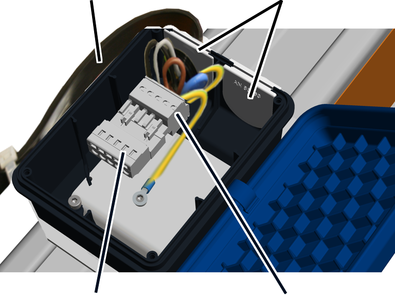
Only with terminal
boxes
|
Mains
power supply |
Cable
bushing |
|
|
|
Pin
multipoint connector |
Bush
multipoint connector |
Connecting supply line (from the mains power supply):
 For mains power supply as
festoon cable system: guide the end of the festoon cable system of the mains
power supply through the cable bushing in the connector housing.
For mains power supply as
festoon cable system: guide the end of the festoon cable system of the mains
power supply through the cable bushing in the connector housing.
 Connect the festoon cable
system (voltage carrying) to the bush multipoint connector. See the wiring
diagram.
Connect the festoon cable
system (voltage carrying) to the bush multipoint connector. See the wiring
diagram.
Screw the protective
conductor with the cable lug onto the base plate.
Connect the protective
conductor from the base plate to the bush multipoint connector (two rows).
With a mains power supply as conductor system: a circuit
isolator is installed on the crane girder, to which the mains power supply is
then connected. See next section.
Connecting the outlet (to the
trolley power supply):
For trolley power supply
as festoon cable system: guide the end of the festoon cable system of the
trolley power supply through the cable bushing into the connector housing and
connect it to the pin multipoint connector.
For trolley power supply
as conductor system VKL: guide the connection cable of the feed unit through the
cable bushing into the connector housing and connect it to the pin multipoint
connector.
For trolley power supply as conductor system KBH: the
conductor system KBH is connected to the mains power supply directly in the feed
unit of the conductor system KBH. This connector housing is not required.
Only with circuit isolator
or housing for fuses
|

|
The figures show the connection to a housing with
fuses and circuit isolator. The connection to a housing with fuses does
not essentially differ. |
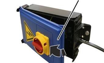
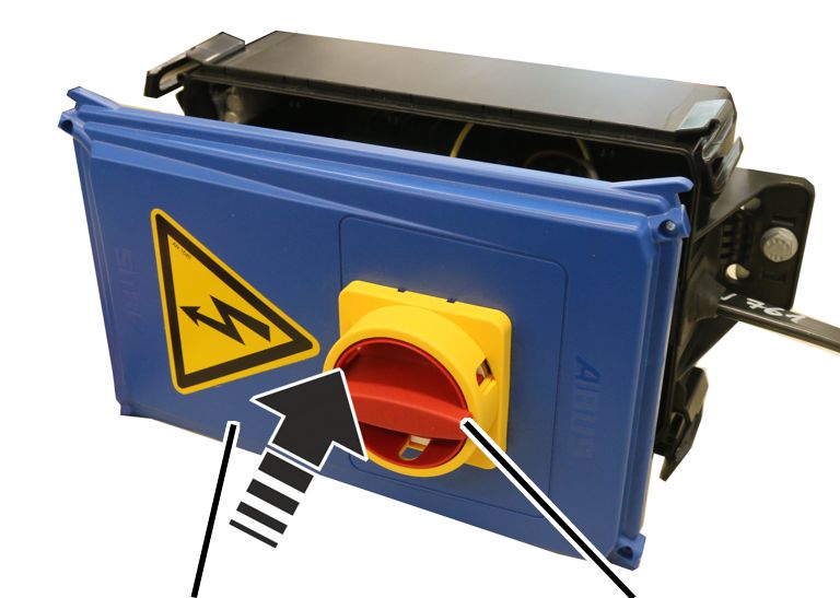
On the housing on the crane girder:
Opening the
housing
|
|
Cover |
|
|
Turn the circuit isolator
to the “off” position.
The cover can only be opened if the circuit isolator is turned
to “off”.
Open the clasps on one side of the housing.
Flip the cover out
laterally.
● The cover
releases automatically from the clasps on the other side when flipped open.
|
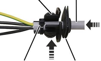
Cable bushing
(as strain relief) |
Connection cable |
|
|
|
Cable
tie |
Cable
bushing (as seal) |
Strip approximately
20 cm sheathing from the connection cables.
Push the connection cable
through the suitable cable bushing (seal).
The housing contains suitable cable bushings for thick or thin
round cables and flat cables.
Push the connection cable
through the cable bushing (strain relief) and fasten it with cable clips.
|
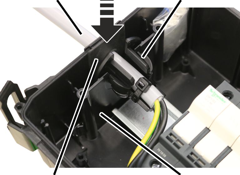
Connection
cable |
Cable
bushing (as strain relief) |
|
|
|
Cable
bushing (as seal) |
Housing |
Push the connection cable
with the two cable bushings into the housing.
─ Push the
mains power supply on the side with the fuse holder into the housing.
─ Push the
trolley power supply on the side with the circuit isolator into the housing.
Insert the rubber lips of
the cable bushing (seal) so that they lay flat against the housing both inside
and outside.
Insert the cable bushing
(strain relief) into the housing as shown in the figure.
|
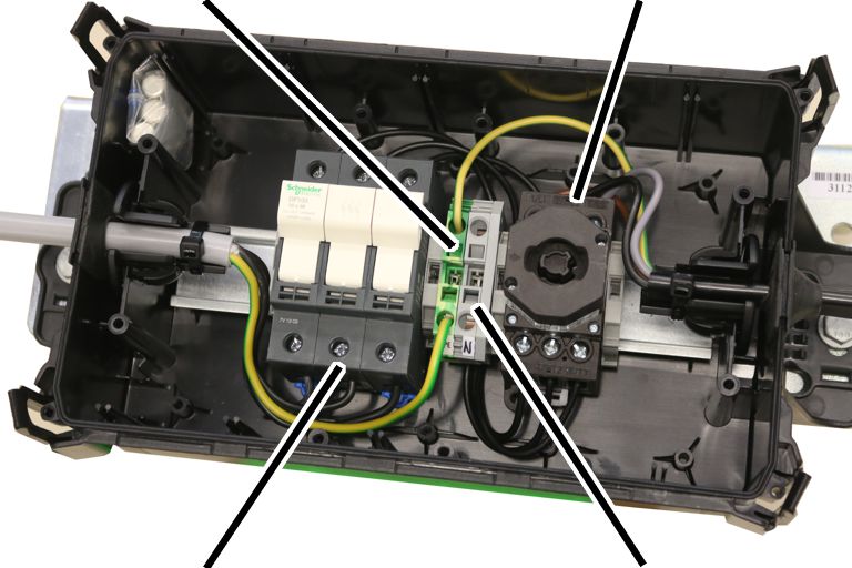
Terminal for protective conductor |
Circuit
isolator |
|
|
|
Fuse
holder |
Terminal
for neutral conductor |
Attach the connection
cable from the mains power supply to the fuse holder.
Attach the connection
cable to the trolley power supply on the circuit isolator.
Connect both protective
conductors to the terminal for protective conductors.
If necessary: connect both
neutral conductors to the terminal for neutral conductors.
|
|
|
Cover |
Circuit
isolator |
Turn the circuit isolator
to the “off” position.
The cover can only be closed if the circuit isolator is turned
to “off”.
Place the cover on the housing so it lies
straight.
Do not first latch and tilt the cover on one side.
Use light pressure to
latch the cover on all four clasps of the housing.